
Key Takeaways
- CNC terminology guide: This guide explains the common terms and acronyms used in CNC machining, such as axes, offsets, speeds, and tools.
- CNC machining basics: CNC stands for Computer Numerical Control and it is a process of using computer software to control the movement and operation of machine tools.
- CNC machining applications: CNC machines can be used to create various parts and products from different materials, such as metals, plastics, wood, and composites. CNC machines include routers, mills, lathes, plasma cutters, and 3D printers.
- CNC machining benefits: CNC machines can produce high-quality, precise, and complex shapes and designs with minimal waste and error. CNC machines can also reduce production time and costs by automating the machining process.
CNC terminology and acronyms can be confusing and technical, especially for beginners. So, we’ve put together this comprehensive CNC terminology guide of the terms often used in CNC machining circles.
From “2D” to “Z-Axis” and everything in between, we help you find this CNC machining terminology glossary useful.
- Key Takeaways
- Terminology Used in CNC
- CNC Terminology and Definitions
- 2D
- 2.5D
- 3D
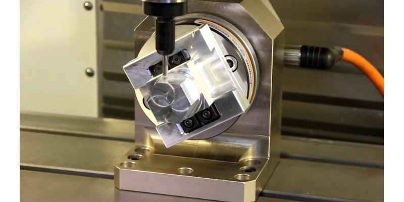
- 5-Axis CNC
- Absolute Coordinates
- Accuracy vs Precision
- Allowance
- APT Programming
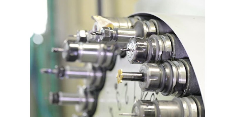
- Arbor
- Automatic Grinding Center
- Automatic Tool Changer
- B-Axis
- Backlash
- Ball End Mill
- Bézier Curve
- Bisect lines
- Boolean
- Bounding Box
- C-Axis
- Center-cutting End Mill
- Centerline Programming
- Chamfer
- Circular Interpolation
- Climb Milling
- CNC
- Control Software
- Conventional Milling
- Conversational CNC
- Coordinate Word
- Corner Overcut
- Corner Radius
- Counterbore
- Countersink
- Counter-drill
- Cutting Depth or Axial Depth of Cut (Stepdown)
- Cutting Force
- Cutting Length
- Cutter Radius Compensation
- Cutter Offset
- Dado
- Dwell Time
- E-stop / Emergency Stop
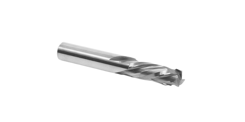
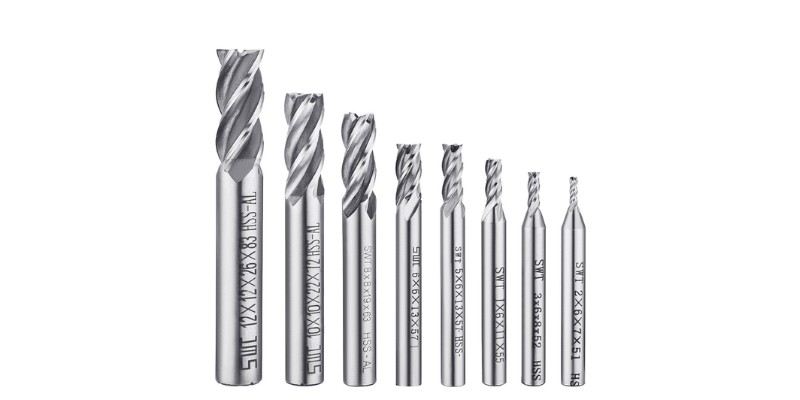
- End Mill
- Extrude
- Face Mill / Face Milling
- Feed or Feed Rate
- Finger Joint
- Finishing Pass
- Firmware
- Fixture
- Flutes
- Flute Length
- G-code
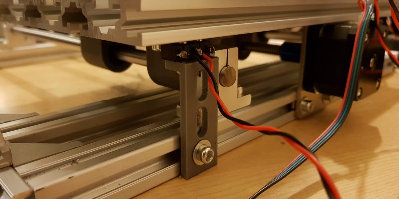
- Gantry
- Groove
- Homing
- Indexing
- Interference and Collision
- Jig
- Jogging
- Kerf
- Limit Switch
- Machining Margin
- Max Depth
- MDI (Manual Data Input)
- NEMA
- Nesting
- Offset
- Peck Drilling
- Plunge Rate
- Pocket Milling
- Quill
- Rabbet
- Rack and Pinion
- Retract Height
- Safety Height
- Speed (RPM and SFM)
- Spindle
- Toolpath
- Vise
- WCS
- X-Axis
- Y-Axis
- Z-Axis
- Final Thoughts
Terminology Used in CNC
Some CNC terminology may be specialized and quite difficult to understand initially. And because if you want to understand everything – or even work in the CNC field – it’s key to understand what each of these terms means.
CNC Terminology and Definitions
2D
What does 2D mean in CNC tooling?
2D refers to a CNC cutting tool that can only operate through two machine dimensions – on the X and Y axes. The simplest example is surfacing, when you go over a large area without moving the tool up and down (changing the cut depth).
Laser and plasma cutting tools are typically only 2D cutters since they don’t need to move the cutting head up and down (though lasers can also have rotary attachments for more 3D work). Any simple computer-aided manufacturing (CAM software) program should be able to handle 2D cutting.
2.5D
2.5D CNC cutting is when you’re able to move the CNC tool up and down during the cutting process. This doesn’t mean moving the tool up and down during the actual cutting, but moving in between cuts.
In other words, a 2.5D operation involves all three axes, but the Z-axis doesn’t move simultaneously with others while cutting.
For example, consider removing 2mm of material, but in two steps (passes): removing 1mm each time. Flat pocketing, some forms of contouring, and V-engraving all happen in 2.5D. Layer printing with a 3D printer also uses 2.5D movements.
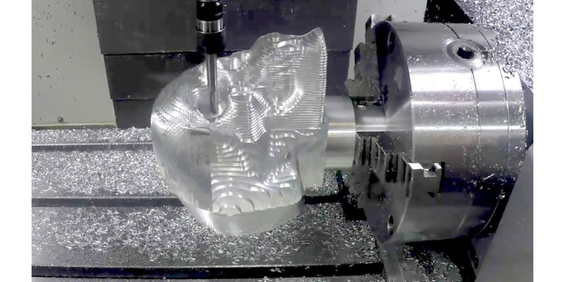
3D
What does 3D mean in CNC terminology?
3D refers to the movement of a CNC cutting tool on all three dimensions simultaneously – the X, Y, and Z axes. In other words, the tool traverses the vertical Z-axis, as well as along the X and Y axes.
3D is used in specialized CAM (Computer-Aided Manufacturing) software and CAD (Computer-Aided Design) software programs, special tooling, or flip jigs as a general design form.
CAM and CAD software enables the best CNC lathes to move in every plane to create a smooth 3D finish. Most 3D tooling is used for machining complex 3D shapes, including components, implants, and different mold types. The tools cut at multiple angles and orientations, allowing for high precision, intricate details, and features to be machined.
Some more basic machines can cut in simple 3D without overhangs using Computer-Aided Design or Computer-Aided-Manufacturing.
The A axis (also the B and C axes)
A 3-axis CNC router can only move on 3 linear axes: X, Y, and Z – like a Cartesian 3D printer. But, there are also 3 rotational axes: A, B, and C.
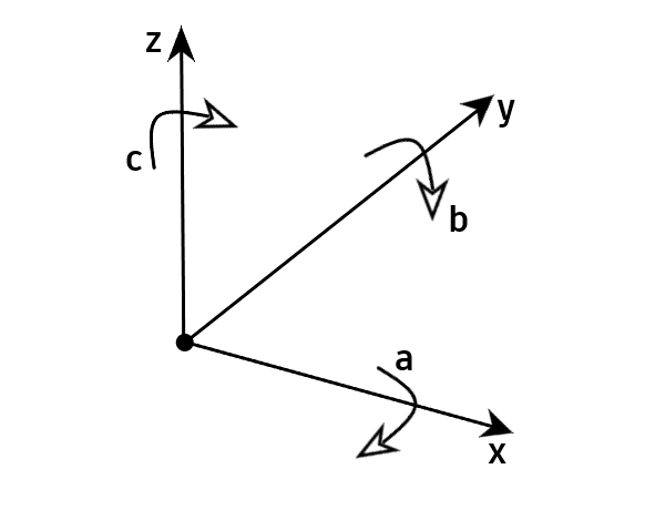
The A axis can turn around a line parallel to the X axis, while the B and C axes turn around the Y and Z axes, respectively (or lines parallel to them). Imagine a CNC machine holding a dowel on a line parallel to X, and turning it (using the A axis) to machine various sides.
Being able to turn on one axis makes a CNC a 4-axis CNC machine, and there are also 5- and 6-axis CNCs. 5-axis CNCs and above are reserved for industrial use and typically cost tens of thousands of dollars, whereas 3-axis CNCs can cost as low as $250.
5-Axis CNC
What is a 5-axis CNC in CNC tooling?
A 3-axis CNC can only machine simple and limited 3D shapes because it can only cut the material from the top, but not other angles. However, a 4-axis CNC can turn the material around its line of symmetry parallel to X, and machine various parts of it, otherwise unavailable to the tool.
A 5-axis CNC can approach the material from all angles. It can do the most complex jobs and create 3D shapes on slanted surfaces as well.
The additional cutting tool, and part tilting and rotating, allow for greater machining flexibility and precision to work with complex shapes. 5D CNC tooling is commonly used to handle the complex geometries associated with high-precision parts.
These machines are commonly used with specialized CAM and CAD software. This generates complex toolpaths for advanced shapes or surface finishes.
Absolute Coordinates
What are the absolute coordinates for a CNC cutting tool?
Absolute coordinates are expressed relative to a fixed position, generally the homing switches (origin points) for CNC machines.
This differs from relative coordinates, which relate to the cutting tool’s current position, like when you zero the tool at a random point on the table.
The coordinates are specified using three axes (X, Y, and Z) that show the tool’s 3D position. The absolute coordinates are programmed into the CNC machine’s control software to steer the tool’s movements, and are usually measured in inches or millimeters.
Accuracy vs Precision
What does accuracy vs precision in CNC machines mean?
In CNC machining, accuracy is the degree of closeness between the programmed position of a cutting tool, and the actual position. In contrast, precision refers to the tool’s consistency in position over repeated movements.
Imagine that you tell two CNCs to cut a 50mm-sided square, the first gives you 50.1mm sides, and the second gives you 50.2mm sides. The first machine is more accurate than the second.
But, you decide to repeat the test 4 more times. The first machine gives 50.05, 50.2, 50.15, and 50.12 mm sides. But the second machine gives you 50.21, 50.22, 50.19, and 50.20 mm sides.
| Measurement | First Machine (mm) | Second Machine (mm) |
|---|---|---|
| 1 | 50.10 | 50.20 |
| 2 | 50.05 | 50.21 |
| 3 | 50.2 | 50.22 |
| 4 | 50.15 | 50.19 |
| 5 | 50.12 | 50.20 |
As you can see, the first machine is more accurate, however, the second machine produces measurements that are more consistent (precise) than the first machine, although the measurements are not as accurate.
This means that the second machine will likely give you similar measurements if you repeat the test, whereas the first machine may give you more variable results.
Mathematically, a more accurate CNC makes smaller errors on average. However, a more precise CNC has less variation across repeated jobs. Here are the average cuts, and the average error and standard deviation between them:
| Machine | Average Cut Measurement | Average Error | Standard deviation |
|---|---|---|---|
| 1 | 50.124 | 0.124 | 0.056 |
| 2 | 50.204 | 0.204 | 0.011 |
As you can see, the first machine makes smaller errors on average (0.124mm vs 0.204mm) so it’s more accurate. On the other hand, the second machine cuts with a much smaller deviation (0.056 vs 0.011), so it’s more precise.
Both are important in CNC machines as they affect the overall consistency and quality of the parts being machined.
Allowance
What is allowance in CNC?
Various processes can leave defects on the part. For example, a sand layer will leave an unsmooth surface, or a fast roughing may leave tiny bumps and surface cracks.
Therefore, to give a high-quality surface finish, the last step is to perform a surface finish operation with the CNC.
Allowance is the thickness of the material to be removed for surface finishing. Too small an allowance may not remove all the defects, while an excessive allowance requires excessive effort, more tooling, energy, and time.
Therefore, the best allowance is an amount that gives an excellent surface finish, with minimum effort (the smallest value that yields acceptable quality).
APT Programming
What is APT programming in CNC?
APT stands for Automatically Programmed Tools. This is the old programming language in the absence of CAMs. It was developed in the 1950s and used instructions to specify tool paths, and developed for the aerospace industry.
Arbor
In CNC, what is an arbor?
An arbor is a device that attaches to the spindle for long machining lengths. It’s like an arm that holds the tool much further so that it can work at a length.
The arbor is generally a cylindrical shaft inserted into the machine’s spindle, with a threaded end to mount a workpiece or cutting tool onto. Arbors come in different configurations and sizes to house various kinds of cutting tools and workpieces.
Automatic Grinding Center
What is an automatic grinding center in CNC grinding?
An automatic grinding center (AGC) is a kind of CNC machine tool that uses advanced automation and high precision to grind and shape metal or other material parts, components, or tools to precise specifications.
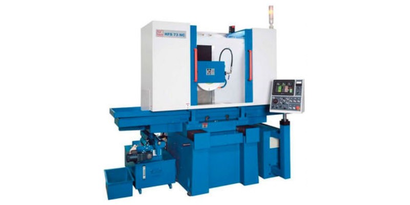
An AGC is physically made up of a grinding wheel and a workpiece holder. It also has a control system to automatically adjust cutting parameters and change grinding tools based on what is needed.
Automatic Tool Changer
In CNC machining, what is an Automatic Tool Changer?
An automatic tool changer (ATC) is a system device that automatically changes CNC machine cutting tools via G code vs M code commands. It typically consists of a control system to lock it in place, and a tool arm or carousel.
ATCs reduce tool changing times by cutting down on the need for manual changing, as an automatic tool changer needs absolutely no human intervention.
B-Axis
Which is the B-axis in CNC tooling?
The B-axis is a rotary axis in CNC tooling, enabling the cutting tool to position at several angles in relation to the workpiece. The B-axis is prominent in 5D CNC machines for machining more complex parts.
The B-axis rotates the spindle or the workpiece in a circular motion around the Y-axis. This means it can reach zones that aren’t otherwise easily accessible to produce highly accurate, complicated geometries.
Backlash
What is a CNC backlash?
Backlash is the linear distance that the nut moves before it engages the screw. When the drive screw-nut system is loose, it may lose part of the movement dictated by the controller, because it’s busy filling the gap between the nut and the screw. In other words, it’s the linear distance that motors are turning without any actual movement.
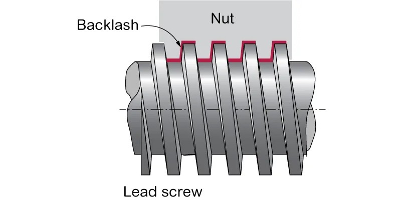
This kind of unexpected play on an axis can lead to inaccuracies in a cutting tool’s position that can result in inaccurate holes or cuts.
The chance of a backlash can be restricted through the use of high-precision components and regular machine maintenance.
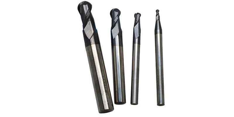
Ball End Mill
What is a ball end mill?
Ball end mills or ball nose end mills are types of cutting tools that have rounded ends. They are used for finer detail passes and smooth contours in complex 3D carvings with the best CNC routers. The rounded ends on these bits produces smooth curves and contours on workpieces that flat-end bits cannot achieve.
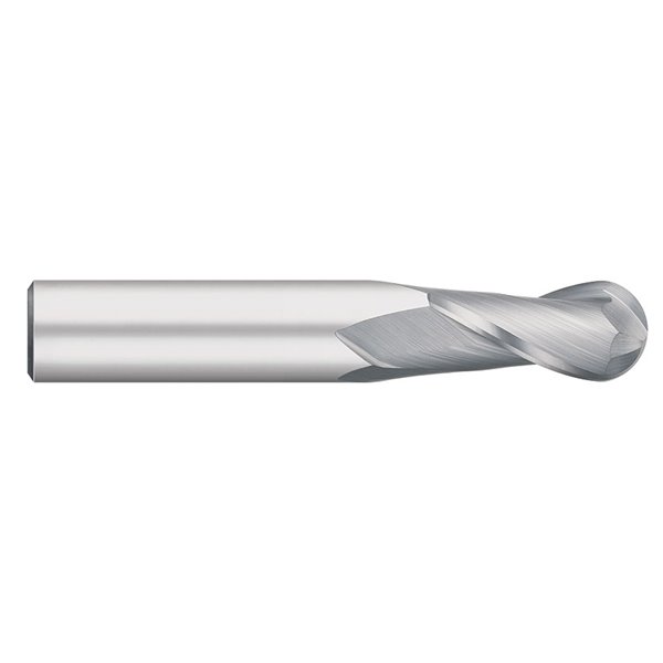
These end mills are generally used for 3D machining and are, as a rule, made from high-speed steel or carbide.
Bézier Curve
What is a Bézier curve in CNC design?
A Bézier curve is a simple curve used in design and computer programs to create smooth shapes. It’s controlled by points that help decide the curve’s direction and shape. In CNC machines, these curves help guide the cutting or shaping tools that pass through specified control points to create precise 2D and 3D designs for various products, such as cars, planes, and artwork.
In CNCs, gcode commands G5, G5.1, and G5.2 will make the machine move on a Bézier curve. Not all CNCs accept these commands. Many entry-level CNCs (for example, those with a GRBL controller) don’t accept commands for Bézier curves.
However, you can use Bézier curves in your designs even if your CNC doesn’t support the command. Your post processor knows how to handle the curves without using the Gcodes for Bézier curves.
Bézier curves are generated by combining polynomial equations of control points with the help of a blending function called Bernstein polynomial.
The number of control points determines the degree of the curve; a higher degree curve provides greater flexibility in shaping complex paths.
Bisect lines
In CNC, what are bisect lines?
Bisect lines are the lines dividing shapes and angles into equal parts. They’re used as reference points to set up CNC machining operations to ensure 45-degree over-cuts of corners that allow slots, pockets, or mortises to be cut using circular bits meant to take square parts.
By using bisect lines to accurately bisect workpiece angles and shapes, CNC machines create the consistent tolerances and dimensions necessary for a range of industrial applications. For instance, bisect curves can be employed to create precise corners and angles in metalworking, to create intricate designs in woodworking, and to shape composite materials in aerospace manufacturing.
Boolean
What is a Boolean in CNC CAD?
A boolean is just a “yes” or “no” option – they’re also used by developers and programmers to execute code based on whether something is true or false. In CNC, a boolean is used to help the machine decide which parts of a design to cut and which parts to keep.
Imagine you have two different colored Lego blocks and you want to join them together. If you put one block on top of the other, they’ll stick together and you’ll have a bigger block made of two colors. But what if you only want to keep one of the colors?
You can use a tool to “subtract” the unwanted color from the block, so you’re left with just the part you want. CNC machines do the same thing with designs – they use booleans to add or subtract different parts of the design, so they can cut out exactly what’s needed.
Bounding Box
In CNC milling, what is a bounding box?
A bounding box is the smallest box you can draw while still holding your bounding object. It establishes the maximum size and dimensions of the specific workpiece. CAD drawings use virtual bounding boxes to estimate dimensions, sizes, and volumes of entire 3D workpieces. These include necessary extra space for fixtures or clamps.
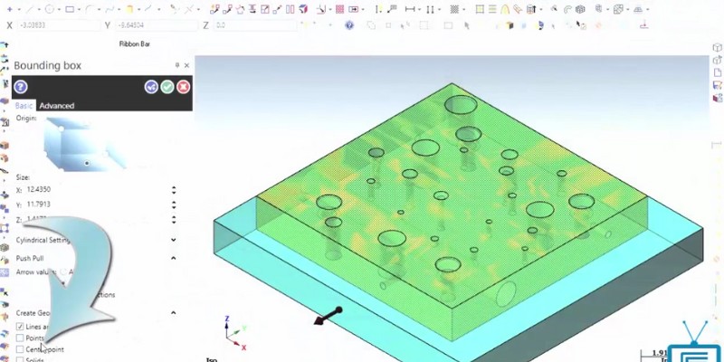
It is an important point of reference when programming and setting up a CNC machine. With a defined bounding box, a CNC controller can properly orientate the machining operation to ensure available space is correctly utilized and not exceeded. CNC milling machines use this method when identifying the initial stock needed to mill a part.
C-Axis
Which is the C-axis on a CNC machine?
The C-axis is the rotational axis around the Z-axis, and can be added to CNC machines that already have a B-axis or an A-axis. It lets the machine spin the workpiece or tool around a central point.
You can’t have a C-axis on its own, but once you have another turning axis like the A-axis, adding a C-axis results in a 5-axis CNC machine. So, 5-axis CNCs don’t necessarily have A and B axes, they can have A and C axes. In fact, the A and C combination is more common in table configurations.
Therefore, the C-axis completes the 5-axis machine and allows it to machine all sides of a workpiece from all angles.
Center-cutting End Mill
What is a center-cutting end mill in CNC?
A center-cutting endmill has cutting blades both on the face and on the side of the endmill. Therefore, it can plunge directly into the workpiece using its face blades, and also move inside the workpiece by cutting with its side blades.
This makes center-cutting end mills ideal for:
- Plunge cutting: Since it can cut at the tip, you can plunge it straight into the material to create holes or slots.
- Slotting: It’s great for creating channels, grooves, or pockets in a workpiece.
- Profile milling: The center-cutting endmill can follow a desired shape or contour on the workpiece’s surface.
- Face milling: You can use it to create a flat, smooth surface on the workpiece.
- Ramp milling: It can cut at an angle, allowing you to create inclined surfaces or features.
Centerline Programming
What is centerline programming in CNC cutting?
Centerline programming is a far less common way of programming a CNC machine, where you specify the tool to move along the CNC cutter’s centerline instead of the edges.
This isn’t common because you have to offset the tool diameter manually. But it affords a machinist greater consistency for using various tools since the resulting G code doesn’t depend on the tool diameter.
Chamfer
What is a chamfer in CNC terms?
In CNC machining, a chamfer is a surface that has been cut with an angled or beveled edge along a workpiece’s corner or edge. Chamfers provide a finished appearance to the workpiece, remove sharp edges, and aid in assembly or disassembly of components.
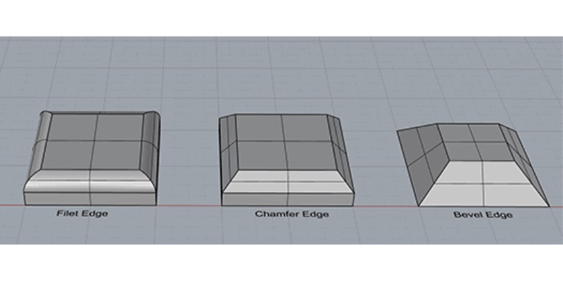
The chamfer angle can vary depending on the application, but common angles include 45 degrees and 60 degrees.
They’re used in creating a decorative edge on furniture or metalwork, reducing stress concentrations in mechanical parts, and improving the flow of fluid through pipes or channels. Chamfers can also be used to create a transition between two different surfaces, such as where a hole meets a flat surface.
Circular Interpolation
What is circular interpolation in CNC?
Circular interpolation in CNC is like drawing a circle with a pen.
Imagine you have a robot arm holding a pen, and you tell it to draw a circle. The robot arm knows where to start and where to end, but it doesn’t know exactly how to move the pen to make a perfect circle.
Circular interpolation is like giving the robot arm a set of instructions that tell it how to move the pen to make a circle. The instructions tell the arm to move the pen in a circular path, starting from one point and ending at another.
In CNC, the machine is like the robot arm, and then the cutting tool is like the pen. Circular interpolation tells the machine how to move the cutting tool in a circular path to make a shape. This is especially useful for carving rounded edges or curved shapes, e.g. the outside of a bowl, or the edges of a gear.
Circular interpolation is a set of G code commands that make the machine move on a circular arc (commands G02 and G03). There are two circular interpolation methods: with R and with IJK.
An axis only moves linearly, so intelligent axial coordination is required by a CNC controller for the feed rate, speed, and direction. Circular interpolation with R needs a feed rate, a radius, a center, an endpoint, and the direction of movement.
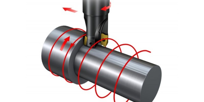
Climb Milling
What is climb milling in CNC milling terms?
When the cutting tool engages the material from the side, the machine can move in two directions. One of these directions is called climb milling and the other is called conventional milling.
For example, imagine that you’re bevelling the right edge of a board and that the tool is turning counter-clockwise as in the picture below.
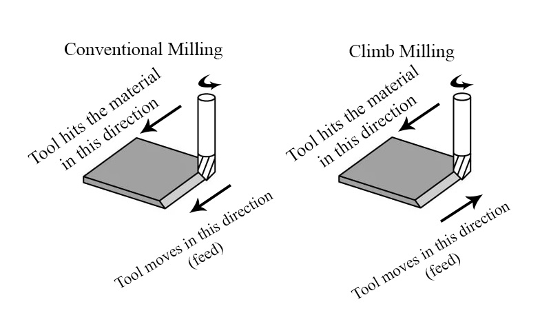
As the image shows, in climb milling, the direction of the feed is the opposite of the direction that the tool cuts the material.
This only works if one side of the tool engages the material (for example, when cutting the side of the material), not when all sides of the tool are cutting simultaneously (for example, when the tool is inside the material).
In climb milling, the tool climbs up the material, meaning it will go up to enter the material from the uncut side. This results in cutting bigger chips, reducing the heat, and increasing the tool life.
The technique is known to decrease the load on the cutting edge and prolong machine tool life. It’s also sometimes used to compensate for the chance of backlash in certain CNC machines.
CNC
CNC stands for Computer Numerical Control. It is called this because the computer controls the movement of the machine by sending the path coordinates and other numbers to the machine. CNC uses a reductive technique, meaning that it produces the product by removing materials from an uncarved block. A CNC machine that uses an additive technique is called a 3D printer instead. 3D printers add materials not remove them.
CNC operators produce engineered finished products, components, and parts using a variety of different materials. These include metals like aluminum, steel, and brass. Materials like plastics, wood, composites, alloys, and certain glass and ceramics are also commonly used.
CNC machines include lathes, routers, and grinders, milling machines, plasma cutters, and EDM machines. 3D printers are also a type of CNC machine.
You control CNC machines with CAD CAM software, which takes a 3D design and turns it into g-code, which are the instructions for where the CNC machine should move and cut the part.
Control Software
What is CNC control software?
CNC control software controls the CNC machine. They send commands to the machine via G-code, waits for it to send the results back, and sends more lines while monitoring and keeping in touch with the machine. Common examples of CNC control software include UGS, Carbide Motion, Openbuild Control, Mach3 and Mach4, and LinuxCNC.
The operator can also interact with the machine via the CNC control software. Some control software also have simulations so the user can see what the machine will do virtually.
Conventional Milling
In CNC milling, what is conventional milling?
Conventional milling or up milling is when the tool cuts the material in the same direction as the feed. It’s used when shaping the side of a material. For example in the image below, the tool is beveling the side of a sheet, and on the left side, the tool feeds in the same direction that it chips the material.

Conventional milling produces significantly smaller chips than climb milling. Therefore, it reduces chip load, increases heat, and reduces tool life. However, it can be compensated by a higher feed rate in roughing.
This is typically used for roughing operations, as it generates more heat and produces a rougher finish than climb milling.
Conversational CNC
What is conversational CNC?
Conversational CNC is a software feature that allows the user to use the CNC without a CAD drawing. The software creates the G-codes by asking the operator questions, instead of creating G-codes from CAD models, saving time when used for simpler operations.
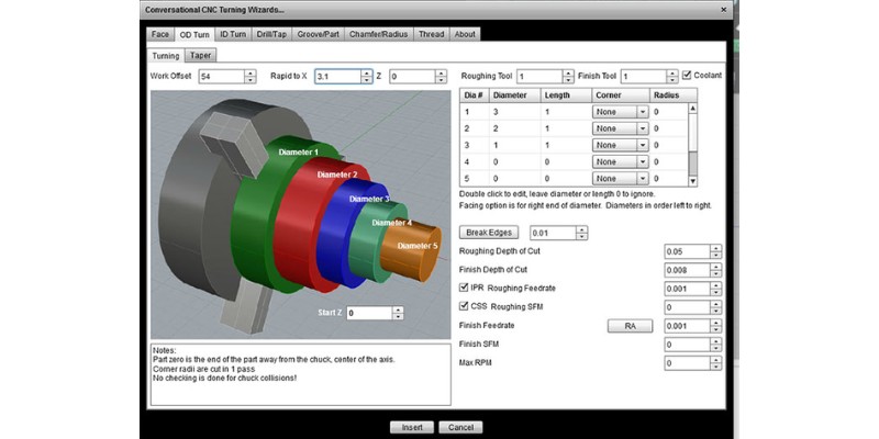
Conversational CNC enables machine operators to use on-screen prompting and plain language instructions through a basic user interface. This also mens operators without any formal CNC programming training can create what’s needed without any complex coding.
Coordinate Word
In CNC G-code, what is a coordinate word?
A coordinate word is a code portion that specifies a point with one or more X, Y, and Z-axis letters and follows a standard G-code motion command. The coordinate word axis values show the cutting tool’s position relative to the workpiece.
Corner Overcut
What is carrying out a corner overcut during CNC milling?
In CNC milling, a corner overcut is a technique that involves intentionally overcutting a corner with a circular path during a profile cut.
This is used to compensate for the fact that a turning tool can never cut a sharp angle’s corner. The corner will always be rounded since the tool is turning. See the image below.
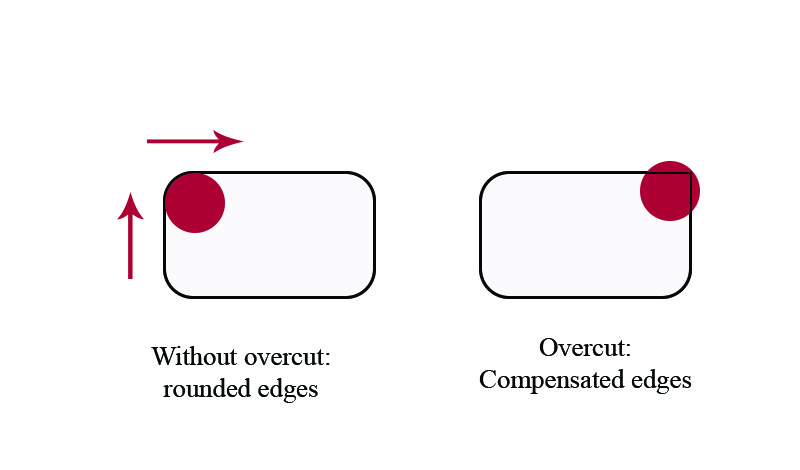
To address this issue, a “dogbone” corner overcut is used, which positions the circular path’s edge at a 90-degree angle – or precisely at the corner of the part being milled. This method ensures that the cutting tool fully reaches the corner, creating a more accurate and smoother surface finish. The dogbone corner overcut not only makes the part look better, but also improves its functionality, especially when fitting with other components during assembly.
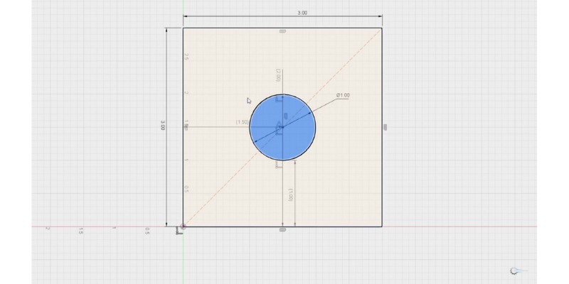
Corner Radius
In CNC milling, what is the corner radius?
In CNC machining a corner (like a square corner), it is uncommon to command the machine to instantly change directions at the corner. Instead, the programmer commands the CNC to follow an arc on the corner.
Therefore, the corner radius refers to the radius of the arc the CNC follows when machining a corner.
If you use a zero corner radius (not recommended), the part’s corner you have machined will be circular (with the same diameter as the tool). See the image below. In this image, the motors follow the blue rectangles and the tool’s perimeter cuts the black rectangles. On the left, the corner radius is zero, while on the right, there is an exaggerated corner radius to see.
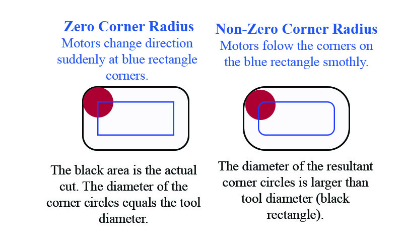
So, even with a zero corner radius, you’ll get a rounded edge. However, you’d also want the motors that follow the blue rectangle to go on a path with rounded corners (like the right side of the image). So, the resulting cut will have circular corners with larger diameters than the tool.
You can compensate for the corner radius by using corner overcutting or corner rounding.
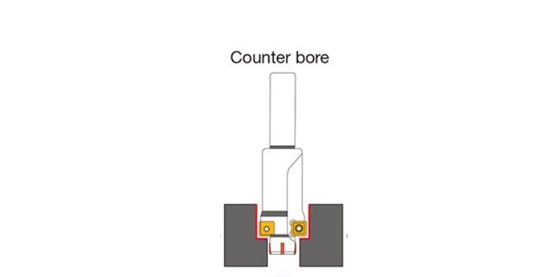
Counterbore
In CNC machining, what is a counterbore?
A counterbore is a larger hole created around an existing hole, making the hole larger so it can be used with a fastener – like a screw or bolt. For example, a screw goes into the hole, while its larger head sits in the counterbore.
Countersink
What happens in CNC machining if you countersink?
A countersink is a conical counterbore (see counterbore above). While a counterbore is cylindrical and has a flat bottom (for ordinary screws), a countersink is conical since some screws have conical heads (many woodworking screws have conical heads).
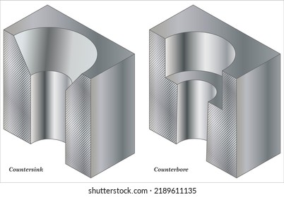
Countersinking occurs when using a CNC drill press to make a conical hole in the workpiece that corresponds with the head size and angle of a certain screw. Countersinking makes sure that the screws used sit flush with the part or enclosure being made.
A countersink means no interference from the fixing which allows for more clearance. Countersinking also allows for a more streamlined finish for aesthetic reasons and it likely provides a better and tighter seal on finished parts or products.
Counter-drill
What happens in CNC machining if you counter-drill?
Counter-drilling in CNC machining is the act of drilling a counterbore or a countersink. A counter-drill is a way of preparing for inserting a bolt or screw head flush with the workpiece’s surface or to create a hole with a flat base.
If the CNC programming is not done properly, or the counter-drilling isn’t carried out correctly, it can result in dimensional inaccuracy, surface damage, or even the breaking of the cutting tool.
Cutting Depth or Axial Depth of Cut (Stepdown)
What is meant by the cutting depth or stepdown in CNC machining?
Cutting depth (axial depth of cut or stepdown) is the depth of material that’s being removed as the tool moves. It shows how deep the CNC has plunged the tool into the material’s uncut surface. Cutting depth means how much is removed in a single pass, not in total. Cutting depth is typically between 0.1 and 1.0 mm.
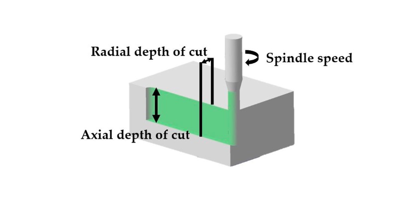
For example, if a CNC removes 2mm of a workpiece in 4 passes of 0.5mm, the cutting depth is 0.5mm, not 2mm.
Cutting Force
What is the cutting force in CNC machining?
Cutting force means the pressure of the cutting tool, and is equal to the resistance of the workpiece against the tool.
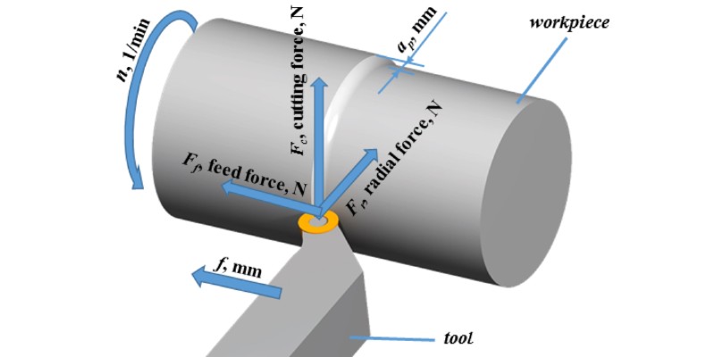
High cutting forces can be inaccurate, due to deflection even damaging or breaking the cutting tool.
Cutting Length
What does the cutting length mean in CNC machining?
The cutting length is the flute or groove length of the cutting edge of the tool that removes the workpiece material. A cutting length is important in determining spindle speeds, feed rates, and cutting depths.
These are needed to achieve exact removal rates of material, in order to maintain optimal cutting tool life while providing dimensional accuracy.
Cutter Radius Compensation
In CNC, what is cutter radius compensation?
Cutter Radius Compensation, also known as Cutter Comp or Cutter Diameter Compensation (CDC), is used to adjust the toolpath based on the size of the cutting tool. It’s essential for maintaining accuracy and precision in CNC operations, as it affects tool wear, tool deflection, and other factors that affect the final dimensions of the machined part.
For instance, when using a cutting tool with a 6mm diameter to machine the outer edges of a part, the toolpath must be offset by 3mm (the tool’s radius) to the outside of the CAD model. If this is not done, the finished part will be 6mm smaller than intended.
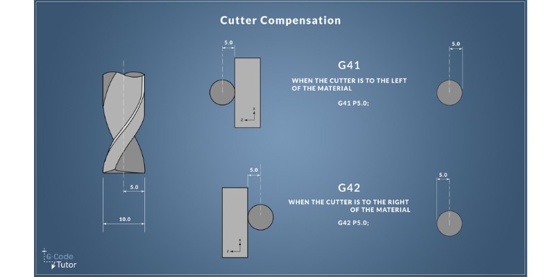
And when creating pockets or internal features, the toolpath must be compensated towards the inside to achieve the desired dimensions.
CNC machines typically use G-code programming to control cutter radius compensation. The following G-code commands are used to manage this compensation:
- G40: Deactivates cutter radius compensation, reverting the toolpath to its original, uncompensated state.
- G41: Activates cutter radius compensation to the left of the toolpath, taking the tool’s radius into account and moving it away from the programmed path.
- G42: Activates cutter radius compensation to the right of the toolpath, also accounting for the tool’s radius and moving it accordingly.
Cutter Offset
What is the cutter offset in CNC machining?
Cutter offset in CNC machining refers to the distance between the Z-axis centerline base of the cutting tool and the workpiece surface.
The control software for the CNC machine sets the cutter offset, which will differ depending on the cutting tool and procedure types.
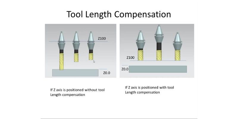
There are two common types of cutter offsets:
- Cutter Radius Compensation (CRC): This offset accounts for the radius of the cutting tool – typically used in CNC milling.
- Cutter Length Compensation (CLC): This offset accounts for variations in the length of the cutting tool – typically used in both milling and turning.
By using cutter offsets, CNC machines can produce parts with high precision and maintain consistent quality, even when changing tools or dealing with tool wear.
Dado
In CNC, what is a dado?
Only utilized in CNC woodworking, a dado is a type of slot cut cross-grain into a workpiece’s surface. Dados are robust woodworking joineries.
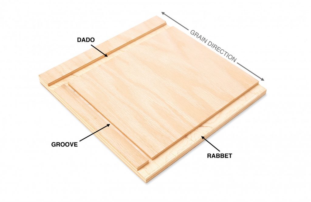
Dados are used to create joints to connect pieces of material to each other, with the width and depth of the same set using the control software of the CNC machine.
The machine will utilize a cutting tool to accurately cut the dado to the specific measurements required.
Dwell Time
What are dwell times in CNC machine operations?
Dwell time means an amount of time that an axis of a CNC machine will “dwell”, meaning it will pause, while the spindles, coolant, and other functions of the machine carry on working.
This dwell time is usually only a few seconds, as any inactivity means a loss of productivity. Most machine operators keep the dwell time as low as possible.
Dwell time is performed with the G04 command on your CNC and is important in the CNC machining process. A newly drilled hole can be cleared of material during dwell time to speed up later production, and it also serves to relieve some of the pressure on a tool.
E-stop / Emergency Stop
What does the E-stop do in CNC machine operations?
E-stop buttons, when activated, are a safety mechanism that cut power to machine components to prevent accidents or CNC operator injury.
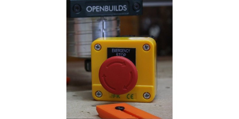
The CNC controller interrupts all power being sent to the drive motors of the axes and to the spindle.
End Mill
What are end mills in CNC milling machines?
End mills are a type of CNC milling cutter used for removing metal from workpieces – like a CNC bit. There are several different types of end mills, and they come in various flutes, lengths, shapes, and diameters.
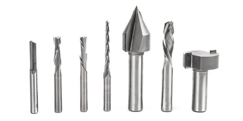
They differ from router bits as router bits have straight edges, while end mills have spiral edges. End mills are better for hard materials.
Some of the different end mills on the market include the ball nose end mill, the square end mill, the taper end mill, the long neck end mill, and the corner radius end mill.
Extrude
In 3D CNC machining, what does an extrude do?
In 3D CAD design, an extrude operation makes a three-dimensional object by moving a 2D shape along an axis. For example, extruding a circle in the XY plane along the z-axis results in a cylinder.
The extrude tool extends a 2D or 3D shape, like a rectangle, into the 3rd dimension by a set height. By extending a 2D or 3D part, an extrude creates a 3D surface or solid. Extrusions can follow a path or taper, extending in any direction.
This process is used to create solid features and parts with a range of different materials.
Face Mill / Face Milling
What is a CNC milling face mill?
A face mill is a cutting tool that CNC milling machines use to remove material from the surface of a workpiece. The face mill’s cylindrical head has many high-speed rotating cutting teeth that cut into the workpiece to remove material and create flat surfaces and complex shapes and designs.
Face mills are mostly used to create flat and even surfaces, to square up the sides of workpieces, and to remove excess material.
Feed or Feed Rate
What is the feed rate in CNC machining?
The feed rate in CNC machining is the speed of the cutting tool’s center moving through a workpiece. Feed rates are measured in either millimeters per minute (mm/min) or inches per minute (IPM). The feed rate specifies the time it will take to remove material from a workpiece, and essentially defines a finished part’s quality.
The feed rate is set by a CNC operator, based on the required quality of the finish, the chip load, and spindle RPM. The greater the feed rate, the quicker materials will be removed, which increases tool life and lowers the time needed, but too high of a feed rate will cause tool breakage. Also, if the CNC machine is not rigid or powerful, high feed rate will cause other problems. You can read more in our article on feed rate, cutting speed, IPM, RPM, and their effects on the finish, tool life, rigidity, spindle power, and more.
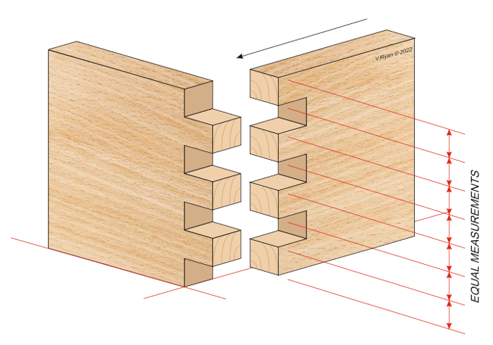
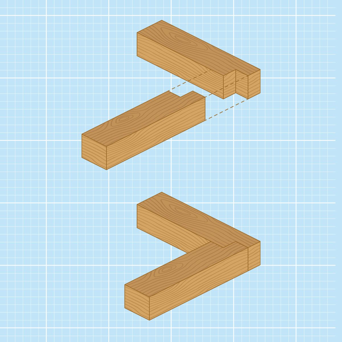
Finger Joint
In CNC woodworking, what is a finger joint?
A finger joint is a joint that creates one large piece of wood by joining two smaller pieces. It is made up of a string of rectangular interlocking projections, or fingers, that are cut into the ends of the wooden sections requiring joining. These fingers connect and fit tightly to make a powerful, stable finger joint.
Finger joints often get used during the construction of furniture, and in many other woodworking assignments.
Finishing Pass
What does a CNC machine finishing pass mean?
A finishing pass is a final cutting operation carried out in a CNC machining task. It is the smooth and accurate final pass, normally done through an extremely thin cut. The finishing pass is undertaken after the last roughing passes are completed to remove any lingering rough spots or imperfections.
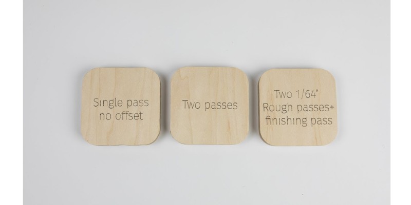
To achieve the pristine surface finish on a workpiece, the depth of cut for the finishing pass are reduced. The feed rate will be slightly increased depending on the depth of cut. If the depth of cut for the finishing pass is too large, however, the feed rate will also be reduced.
Firmware
What is the firmware for G-code in CNC?
CNC firmware is software inside the CNC controller that picks up the G-code commands that CAM software generates, and then translates them into specific machine movements for cutting your workpiece.
Firmware also deals with other CNC machining functions like input/output communication (I/O), motor control, and feedback control. Without firmware, your CNC would be useless.
Fixture
What is a CNC fixture?
A CNC fixture is a machine tooling device designed to hold specific parts of a workpiece securely in place during CNC machining.
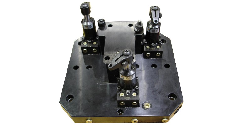
It is specially designed to make sure the positioning of a part is accurate, thereby reducing the chance of any errors taking place. These fixtures could include pins, bolts, clamps, or a range of other fasteners.
Flutes
What are flutes in CNC?
Flutes are the sharp edges that rise helically on the CNC bit and do the cutting. The flutes channel debris and chips away from both the cutting tool and the workpiece to reduce the friction and heat generated during cutting.
The shape, spacing, and number of flutes affect the performance of the end mill or bit, the clearance rate of any debris, and the finish on the workpiece surface.
Flute Length
Flute length is the length of the cutting portion of a drill bit or end mill, from the flute end to tip. The length of a flute affects how rigid and stable a flute is, and ultimately its performance due to the depth it’ll be able to cut into a workpiece.
Longer flutes may not be as rigid, increasing the deflection or chatter risk, but they can make deeper cuts. Flute length should be considered when choosing a cutting tool for your specific CNC project.
G-code
What is G-code in CNC machining?
G-code is the programming and coding language used to instruct a CNC machine. It is responsible for the operation of the CNC machine, and is a series of instructions, such as for the feed rate, tool path, speed of the spindle, and more. CAM software generates the G-code. The operator may also directly write G codes for simple cuts.
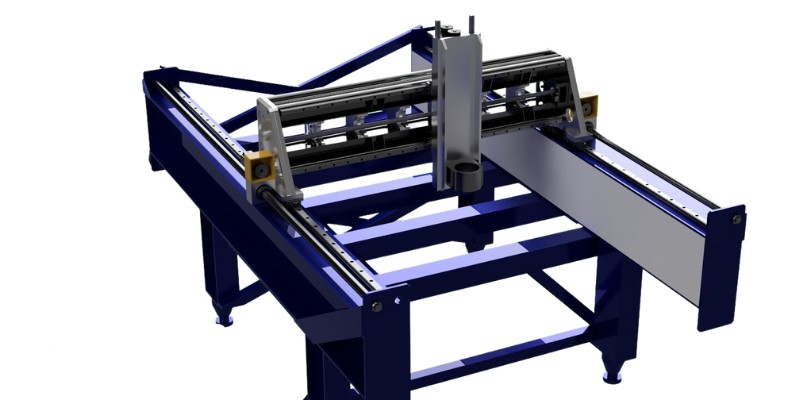
Gantry
What is a CNC gantry?
The gantry is the design where a rigid frame holds the spindle and the X and Z axes and moves across linear or guide rails.
Gantry CNC machines are used in:
- Routing: Gantry CNC machines are used for routing on large workpieces, such as large panels in woodworking.
- Plasma, laser, and waterjet cutting: The gantry design provides the necessary rigidity and accuracy for these high-precision non-contact cutting operations.
- 3D printing: Some large-scale FDM 3D printers use a gantry system to accurately position the print head over the build area.
Groove
What is a groove in CNC machining?
Grooves are long, narrow trenches or slots that CNC machine tools cut into workpieces. A groove will normally follow the material grain (for either functional or decorative reasons). The groove’s size and shape can be specifically controlled using CNC machining techniques.
Types of groove include:
- Through-grooves: Pass directly through the material from one side to the other
- Stopped grooves: Housed within the material, one or both ends of the groove is inside the material. So, the groove doesn’t pass from one side to the other (as a through groove does).
Homing
In CNC machining, what is meant by homing?
In CNC machining, homing is where a machine’s cutting tool or workpiece is exactly positioned at a certain reference point on the X, Y, or Z-axis. This is typically carried out at the start of a CNC machining operation.
Homing is performed by moving the workpiece or cutting tool to a designated position using a G-code command. This is aided by limit switches to identify the axial positions. Homing ensures the correct calibration of the machine tools to allow for repeatable machining without excessive tool wear.
Indexing
What is indexing in CAM and CAD software?
Indexers are motion devices that allow rotating around an axis. They are the simplest form of adding a rotating axis to a CNC. For example, a rotary 4th axis may use indexing to machine the workpiece from various angles.
Indexing in the CAM software works in tandem with the rotary. The crucial aspect of indexing is that the indexer never moves while the tool is machining.
This means more elaborate and detailed machining can be carried out, like drilling holes at unusual angles or creating curved surfaces in CNC milling. The software controls the indexing, which can be used in tandem with other machining strategies.
Interference and Collision
Interference occurs in a CNC when unwelcome electromagnetic waves from the spindle reach the controller and affect its signals. These disturb the controller, interfere with the machine’s movements, and result in the CNC not working properly.
Often, both CNC spindles and controllers have the equipment to inhibit this problem. But there are other measures like keeping the controller and its cables as far as possible from the spindle’s power cables.
Collision occurs when a cutting path or tool makes contact with other CNC machine parts or the workpiece. This can result in damage to the cutting tool, the workpiece, or the machine itself, often ruining the part.
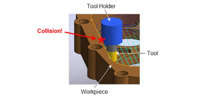
CAD CAM software include algorithms to identify potential collisions and prevent interference, but the correct programming and setup is still vital.
Jig
A jig is a specialized holding tool or fixture designed to securely hold material and guide the cutting tool during manual CNC machining. Jigs can also be useful during the setup and alignment of the cutting tool and workpiece, thus reducing any chance of mistakes.
Jogging
In CNC machining, what is jogging?
Jogging is a manual mode when a CNC operator moves an axis manually in slight increments. This enables more precise positioning of the project or the cutting tool, and is often used during setup, inspection, or when changing a tool.
The direction and distance of a jog are often done with a handheld jogging pendant control or occasionally through software commands to regulate the jogging speed.
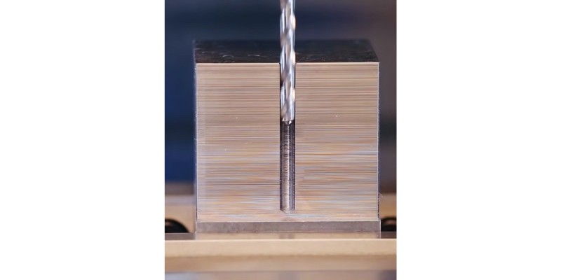
Kerf
In CNC machining, what is the kerf?
The kerf refers to the cut width of material removed by the cutting tool through the CNC machining process. The size of the kerf depends on the diameters of the machine tools used, the angles of their cutting edges, along with what material is being machined.
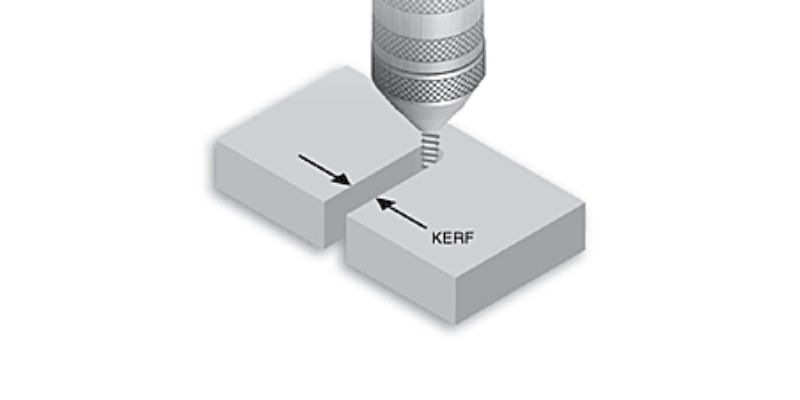
CNC machine operators should keep accurate accounts of the kerf to ensure detailed machining and keep any errors in the workpiece’s finished dimensions to a minimum.
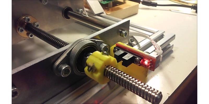
Limit Switch
What is a CNC limit switch?
CNC limit switches prevent crashes from over-traveling that could damage the machine and your current project. A limit switch is a switch or sensor placed to trip an e-stop at the axis end in case the axis reaches that point.
The switch also signals the CNC controller when a moving machine part reaches that specific position.
In theory, a CNC controller should always have a limit switch at each end of a machine if all axes are in operation. Certain belt-driven designs allow for only one, though.
Machining Margin
What does a machining margin mean?
The machining margin is how much outside the design’s perimeter the cutter is allowed to go.
Some CAM software features need a slight margin to work. For example, if you want to insert the tool in a helical motion instead of a direct plunge, you’ll need some machining margin.
Max Depth
What is CNC max depth?
The max depth is the deepest that a CNC program allows the machine’s cutting tool to cut.
The maximum depth is determined by factors, including the length and diameter of the cutting tool, the length of flutes or blades, the type of material, and the type of machining being carried out.
If the max depth is surpassed, it could break the tools, the machine, and the workpiece.
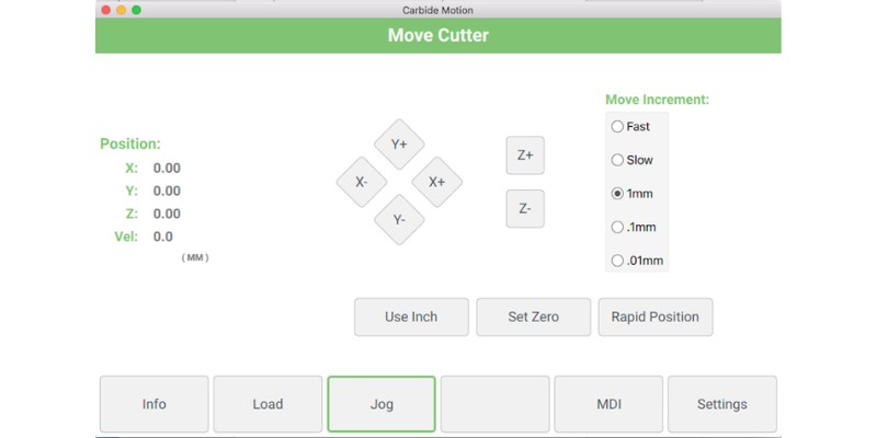
MDI (Manual Data Input)
In CNC, what is MDI?
MDI is a feature in some CNC control software. Manual Data Input (MDI) is part of the interface where the CNC operator uses a keyboard or other device to manually enter commands into a CNC machine to jog the axes, move the cutting tool, execute a line of code, etc.
MDI is also used for troubleshooting or testing commands without using a prewritten program or file.
NEMA
Who is NEMA?
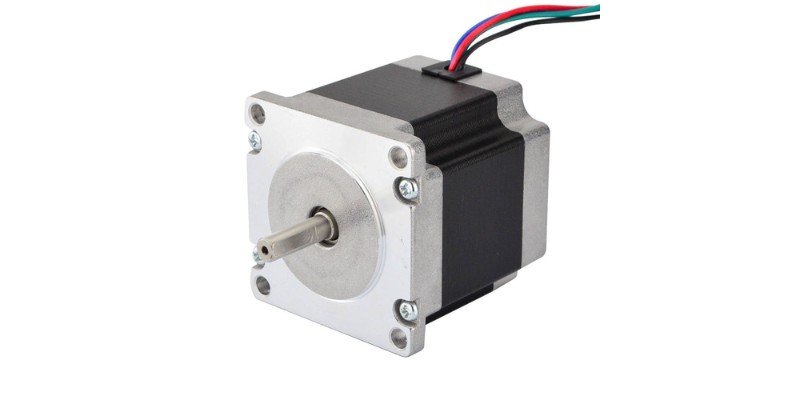
NEMA stands for the National Electronic Manufacturers Association. This is the standard-setting body for CNC electronics enclosures. NEMA has set the standard on the size of stepper motor face plates. For example, a NEMA 23 stepper motor will have holes that are 2.3” apart.
Nesting
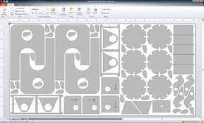
What is nesting in CNC?
2D nesting is the act of arranging the 2D parts (shapes) on a sheet so that they take up the smallest area. This way, the CNC can cut all the parts on the smallest possible sheet, and with the least possible waste on a sheet – to save money. A similar concept applies to 3D.
Nesting is an optimization problem in mathematics: lay out all the shapes so that they don’t interfere and they take up the smallest volume or area.
Nesting software arranges these parts to increase cutting efficiency and reduce waste on a material sheet. This is done to reduce costs by saving excess waste through optimal cut pattern design.
Offset
What are offsets in CNC control?
Offsets in CNC tell the machine to perform its motions at a defined distance (offset) to compensate for something. For example, if you insert a router bit that is 2” longer, the CNC has to move to a plane that’s 2” higher to compensate for the added tool length. This is the height offset or the tool length offset.
The various CNC offsets include diameter offset (G40 to G42), height offset (G43), and work offset (G54 to G59).
Peck Drilling
What is peck drilling in CNC operations?
Peck drilling is a CNC drilling technique used for drilling deep holes in the material. This involves inserting a bit into a hole, and then retracting it on occasion to remove chips and cool down the bit. It’s generally used when holes are several times deeper than the bit’s diameter.
This means deeper and more precise drilling takes place. Cooling the bit on occasion, and even pouring coolant into the hole, reduces the chances of it breaking, while also minimizing damage to the workpiece. Peck drilling is often used for drilling brittle or hard brittle materials.
Plunge Rate
What is the plunge rate in CNC cutting?
The plunge rate is the speed at which the router bit is plunged into the workpiece when you start cutting. There is no ideal plunge rate, as it varies based on the material being cut, and the bit being used. It is important not to plunge too quickly as this could damage to the cutter.
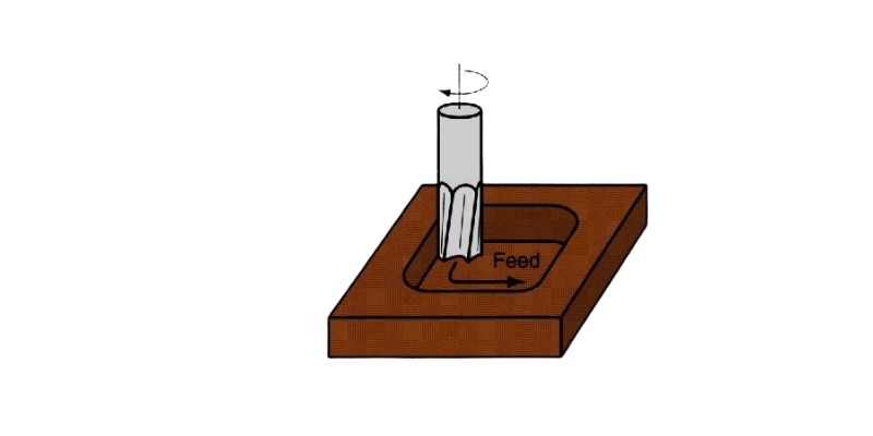
Pocket Milling
What is CNC pocket milling?
CNC pocket milling is a machining technique that removes materials from a workpiece to create a cavity or pocket. This involves removing the material in a number of passes and deepening the pocket using a cutting tool.
Quill
What is the CNC quill in milling operations?
In CNC milling operations, a vertical component called the quill, using a rack and pinion, lifts and drops the spindle cartridge on a drill press and manual milling machine to adjust the depth of cut. The quill is typically found at the end of the milling head and its height gets adjusted either manually or automatically by the CNC machine.
The quill is also used for drilling, in which a cutting tool plunges into the workpiece to make cavities or holes.
Rabbet
In CNC machining, what is a rabbet?
In CNC machining, a rabbet is a recessed groove in a workpiece edge that another piece will fit into as a joint.
Rabbets can suit various joint designs depending on the depth and width they’re cut to and are common parts for woodworking applications like cabinets, and furniture.
CNC machines can repeatedly produce specific rabbets quickly and easily.
Rack and Pinion
What is a CNC rack and pinion?
In CNC machining, a rack and pinion is the drive system that many CNC setups use. It is a linear actuator that translates rotary into linear motion. The rack is likely made of an angled or flat bar lined with teeth, and the pinion is a connected gear that rotates to shift the rack.
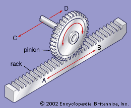
CNC gantry systems and those used in linear motion utilize rack and pinion systems to move cutting heads along fixed axes.
Retract Height
What does the CNC retract height axis term mean?
The retract height is the height that the cutting tool on the Z-axis lifts above the workpiece after the CNC machining operation in order that the material isn’t damaged by the bit. The retract height is also known as the safety height, and also makes removing debris from the work area easier.
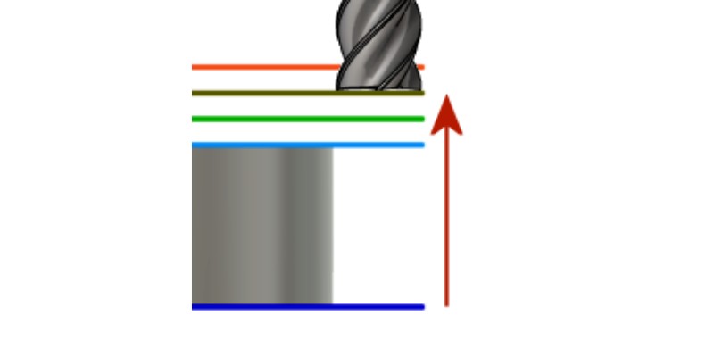
The retract height is normally pre-programmed at a safe height prior to starting a project.
Safety Height
What is the definition of safety height in CNC?
See “retract height” above.
Speed (RPM and SFM)
What does the speed mean in CNC?
There are several speeds in CNC machining.
Spindle speed is how fast the spindle turns: it’s the number of turns the spindle spins in a minute, or RPM.
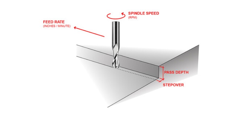
Surface speed or cutting speed is how fast the edge of the cutter travels relative to the workpiece due to the spindle’s rotation (not due to the feed rate). It can be measured in m/s (metric meters per second), SFM (feet per minute), IPM (inches per minute), or IPS (inches per second).
Spindle
In CNC, what is the spindle?
The spindle holds the cutting tool on a CNC machine. It is the rotating component that rotates the tool for high-speed cutting, shaping, or drilling of the workpiece.
Spindles are often powered electrically, but can also run hydraulically or via other methods, depending on the CNC machine being utilized. A router is sometimes used instead of a spindle.
Toolpath
What is the CNC toolpath in machining?
In CNC machining, the toolpath is the map or route that a cutting tool is guided on to machine a component or part. This route is defined by your software through instructions called G-code, generated for a CNC machine to follow. This includes the direction and speed of the cutting tool meaning that the toolpath is a critical part of the overall CNC machining process.
The toolpath is very important for accuracy and shape – and a good toolpath can lower costs, shorter production times, and create better-finished parts.
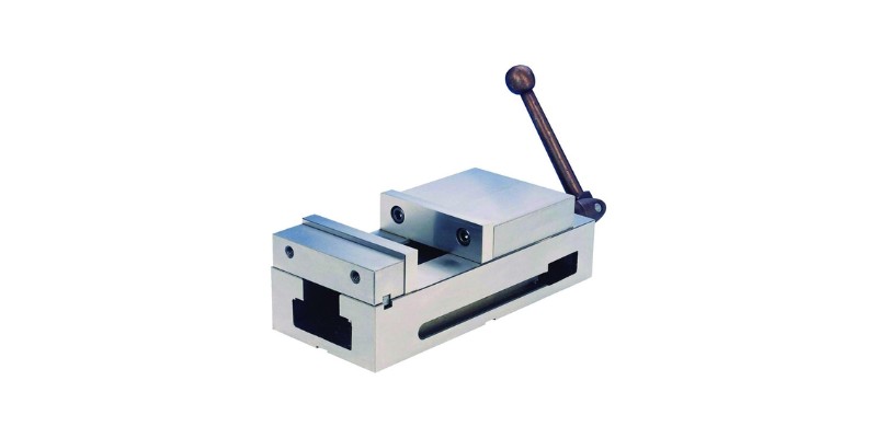
Vise
What is a vise in CNC machining?
A vise securely holds a workpiece during a machining or woodworking process. The vise can come in several different sizes and is normally metal with jaws that open and get clamped together using hydraulic pressure or a screwing mechanism. It is likely either connected to work-holding fixtures or the CNC machine table.
WCS
What is WCS?
WCS stands for Work Coordinate System. The WCS is defined by the operator or the programmer in the CNC machine’s software. It is used as a reference for all machining operations after that. The WCS details the part’s position in relation to the cutting tool.
X-Axis
In CNC, which is the X-axis?
The X-axis is the left-to-right horizontal axis of the cutting tool along a workpiece and is responsible for holding the workpiece in place. It is one of the three primary linear axes in CNC that make up the machine’s coordinate system.
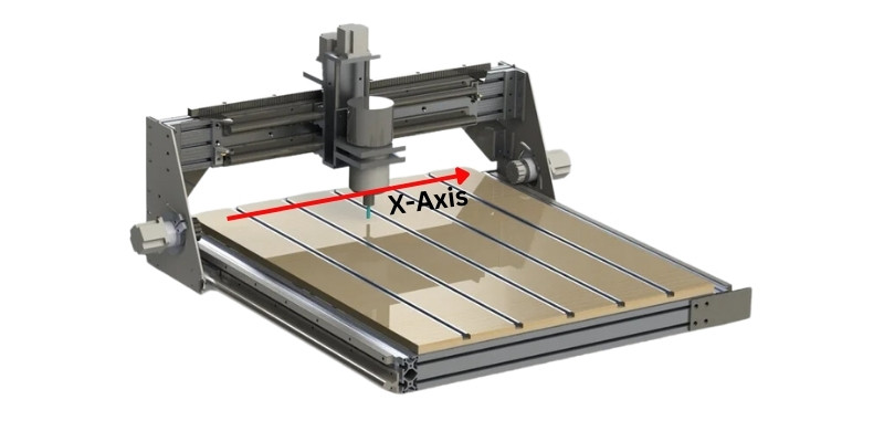
The X-axis is perpendicular to the Y-axis and Z-axis, which account for the vertical and depth movements.
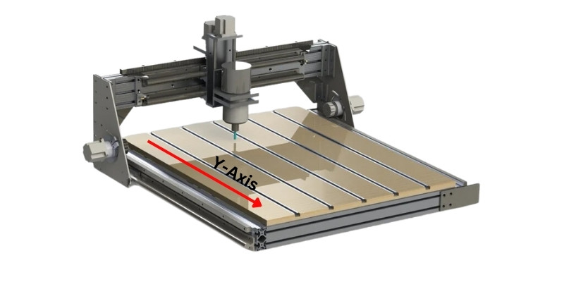
Y-Axis
In CNC, which is the Y-axis?
The Y-axis is the front-to-back or back-to-front vertical axis positioned perpendicular to the X-axis and Z-axis. It accounts for the CNC cutting tool’s vertical movement along the workpiece and is used for creating features and cuts extending along the workpiece’s length.
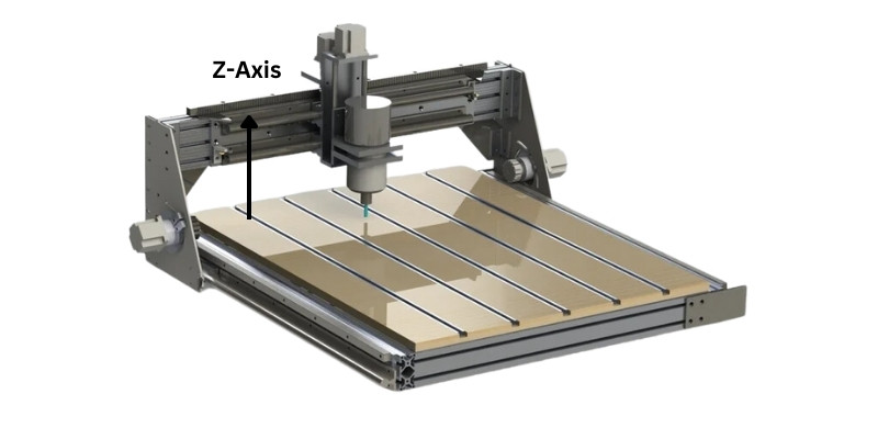
Z-Axis
In CNC, which is the Z-axis?
In CNC, the Z-axis represents the depth movement of the machine tool into the workpiece, either from top to bottom or bottom to top, depending on the orientation of the CNC machine. It is oriented perpendicular to the X-axis and Y-axis and is utilized to carry out depth-related cuts and features or 3D contouring.
Final Thoughts
In conclusion, CNC machinery terminology is essential for you to know if you intend to work in the CNC industry. Even some of the most common CNC terms may be technical in nature, but you should know them to communicate efficiently and effectively in CNC circles.
Although we’ve provided a comprehensive guide to CNC machining terminology used in the industry, it is important to note that it is by no means exhaustive. There may be added terminology used in specific applications and industries.
This guide will give you a good starting point when looking to learn more about CNC. We’re sure to have a CNC terminology PDF available soon for download too!
- NC vs CNC Machines – The distinguishing factors explained
- Best CNC mills (The most affordable milling machines now!)
- Best laser cutters for new & small businessess
- What are the main types of CNC machines? Guide
- software