Engraving tumblers, mugs, and yeti cups is becoming more and more popular, and they sell really well online and at craft shows.
But, if you’re worried about getting it wrong and ruining an expensive tumbler, then don’t fret – I’ll show you exactly how to engrave one in Lightburn. I’ll cover every important step, along with screenshots and a video I’ve recorded – as well as my method for orienting the design in Lightburn.
What You Need to Engrave a Tumbler
- A laser machine (you can read our guide to the best types of lasers for tumblers and our recommendations here)
- A rotary
- A tumbler!
If you have all these, let’s get started!
Preparation
Often your design will be a raster design, with a transparent background. For this example project, I’ve created a raster design with a transparent background for engraving.
You’ll also need to set up your rotary within your laser. With an open air diode laser this is easier, but for some enclosed CO2 lasers you’ll need a riser base, or to remove the tray, etc.
Then, to align the tumbler correctly, use your jig so that the rotary lies perfectly along the X-axis. The tumbler should be level, with the top side facing the laser completely flat.
So, if the tumbler is conic, you should adjust it so that the top side still looks flat and level from the laser’s view.
To align a conic tumbler in a chuck rotary, you have to put something under one end of the rotary so that the tilt compensates the slope. For roller rotaries, you should use the level adjustment (if your rotary has this).
Now, you’re ready to get set up in Lightburn.
Laser Engraving Tumblers With a Rotary in Lightburn
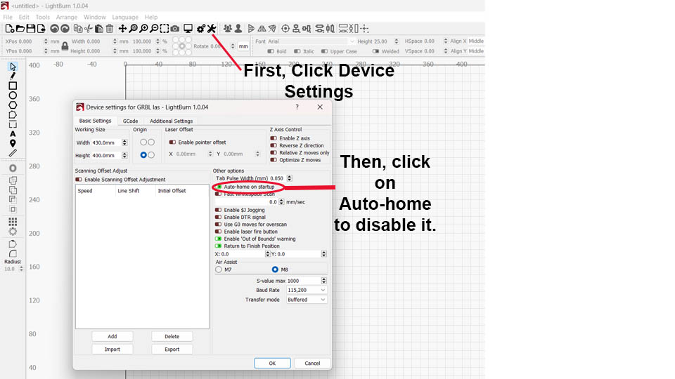
1. Disable Auto-Homing
You should disable auto-homing for engraving tumblers. If your laser machine has a dedicated axis for rotary engraving, you don’t have to disable auto-homing but for machines that attach the rotary motor to the Y-axis socket, you must disable auto-homing.
You can disable auto-homing in the device setting. To open the device setting, in the top tabs, click Edit > Device Setting, or simply click on the icon I’ve shown in the image below.
Also, on the left of this box, make sure that your laser origin is set correctly.
2. Orienting the Design
After you import and scale your design, you should rotate it -90° or +90° to flow along the rotary on the X-axis.
You can do it by typing -90° in the Rotate field with the design selected, as shown in the image below:
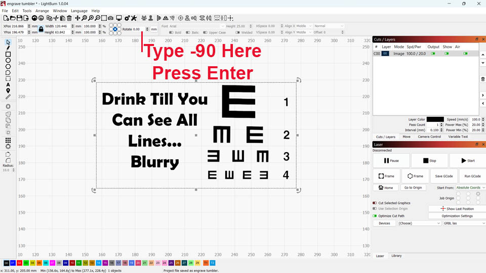
(Don’t worry about which is right out of +90° or -90°, just choose one of these, I have a method to fix any orientation issues later on in this article.)
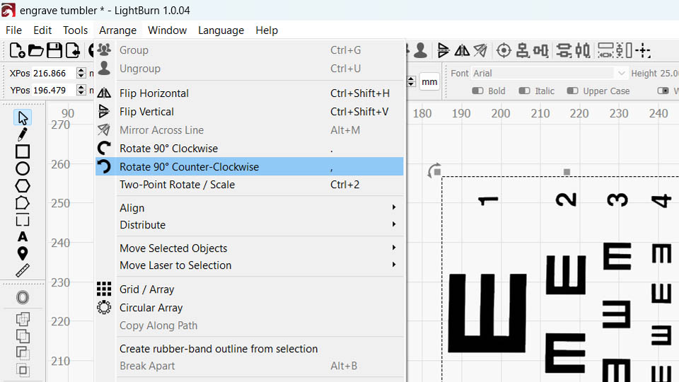
Alternatively, you can click Arrange> Rotate 90° Counter-Clockwise as in the picture below (or Rotate 90° Clockwise if you want to rotate 90°).
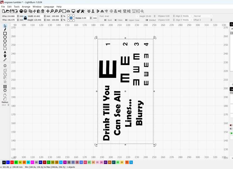
This is what the result should look like:
However, if your laser rotary connects to the X-axis (which is rarer), skip this step.
3. Rotary Setup
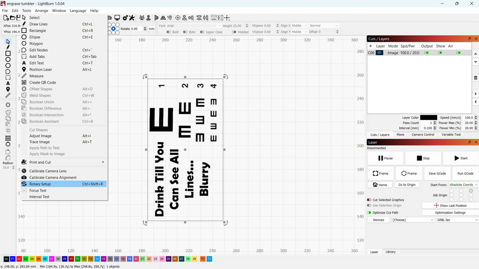
Open the rotary setup dialogue by clicking Tools> Rotary Setup or using the shortcut keys Ctrl+Shift+R.
The image below shows the rotary setup dialogue. Here, choose chuck or roller depending on which rotary you have. Then, click Enable Rotary. Don’t enable “Mirror Output to Rotary,” as I’ll explain it later.
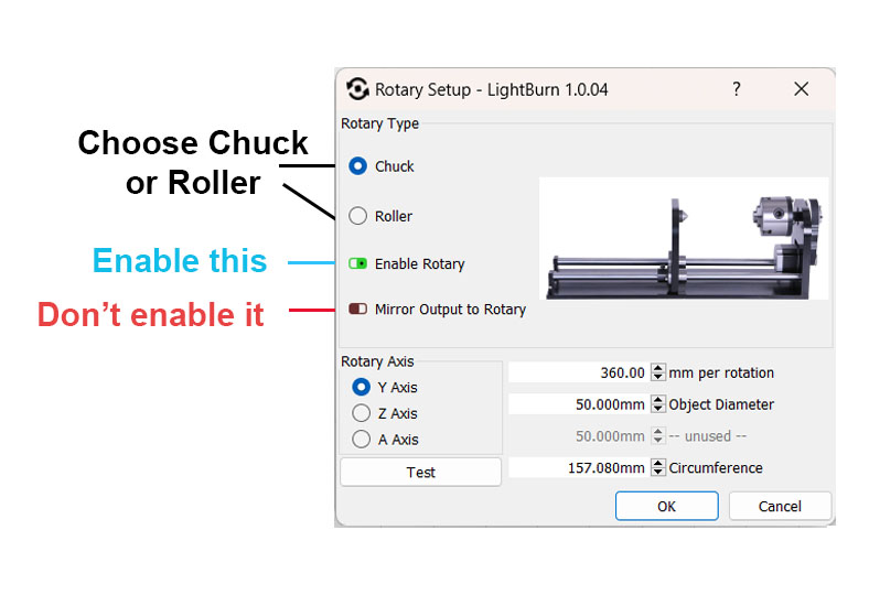
In the Rotary Axis part on the bottom, you should choose the axis your laser uses to turn the rotary. For most lasers it’s the Y-axis, so leave it, but some DSP controllers use another axis for this.
Set mm per rotation
Next, you should enter the mm per rotation for your rotary. This number tells Lightburn how to stretch the image on the rotary axis.
You can calculate mm per rotation by understanding which number, when you press Test, causes the rotary to make one full 360° rotation.
My favorite method for getting a ballpark figure is to get a tumbler, and attach masking tape around it. Then, mark the beam spot on the tumbler. Now, in the mm per rotation, enter a guess, for example, 24mm, and press Test.
The rotary will turn, and when it stops, mark where the beam points now.
Next, measure the length of the masking tape between the two marks. You can use a tape measure without removing the masking tape, or remove the masking tape and use a caliper or ruler.
Then, use this formula to calculate: mm per rotation = 24*circumference/length traveled. If you used some other number instead of 24, use that number instead.
For example, let’s say I entered 24mm per revolution, the tumbler circumference is 200mm, and the length of masking tape between the marks turned out 100mm. We have mm per rotation = 24*200/100 = 48. So, enter 48 for mm per rotation.
While this can be slightly off, it’s a quick way of getting pretty accurate results.
The other way is just to put one piece of masking tape on the chuck or roller and mark its top. Then, try different numbers for mm per rotation until you find the number that makes the mark turn a full 360°.
Measure Object Diameter or Circumference
You also need to measure either the tumbler’s circumference or its diameter. Once you know one, Lightburn automatically calculates the other.
The best method is to use a caliper, but you can also use a tape measure.
Set Roller Diameter for Roller Rotary
If you have a roller rotary, you need to know the roller’s diameter. Look it up in your rotary’s manual, or measure it with a caliper.
Then when you’ve completed all these steps, click OK to close Lightburn’s Rotary Setup Dialogue.
4. Flipping / Mirroring Your Design (Only If The Wrong Way Around)
If your rotary is turning in the opposite direction it should, or if you’ve rotated the design the wrong way in the previous orientation section, then you might need to flip the design horizontally, vertically, or both (mirroring against the local y-axis and x-axis) before starting your engraving.
I’ve devised a method that tells you if you need to mirror the design, without requiring a test engraving.
In this method, you’ll write down values (+1 or -1) from the table below, and multiply all the values. If the result is -1, you must flip the design vertically. If the result is +1, you don’t need to mirror the design.
Though, make sure your laser origin was set before importing the design, because if you set it afterward, Lightburn may automatically mirror it. Also, motor direction is always determined by looking at it from above while the motor shaft extrudes away from you. See setting mm per rotation for sending + movement signals to the motor.
| Factors for Vertical Flipping (x-axis mirroring) | Values |
|---|---|
| Where is your laser origin? (*See explanation below) | Rear left: -1 Front left: +1 Rear right: -1 Front right: +1 |
| How did you rotate the design after import? | 90° counter-clockwise: +1 90° clockwise: -1 |
| Rotary type | Chuck: +1 Roller: -1 |
| Rotary’s direction of positive movement (**See explanation below) | Counter-Clockwise: +1 Clockwise: -1 |
| Rotary position (direction) | Motor mount towards +X: +1 Motor mount towards -X: -1 |
| Tumbler orientation | Tumbler’s bottom toward +X: +1 Tumbler’s bottom towards -X: -1 |
If you think testing is easier, you can wrap paper around a mug and engrave it at low power to see the results. The disadvantage of “just testing your setup” is you won’t know about any other contributing factors; so you may inadvertently change something without realizing you’ve changed the mirroring requirement.
For example, in this forum, some users have got mixed results. Their engravings were sometimes fine, yet mirrored at other times.
The table below shows the factors to consider for flipping horizontally. After you write down +1 or -1 for each row of the above table, multiply them. If the result is -1, you should flip the design horizontally, but if the result is +1, leave it alone.
| Flipping Horizontally (y-axis mirroring) | Values |
|---|---|
| Where is your laser origin? | Rear left: -1 Front left: +1 Rear right: +1 Front right: -1 |
| How did you rotate the design after import? | 90° counter-clockwise: +1 90° clockwise: -1 |
| Rotary position (direction) | Motor mount towards +X: +1 Motor mount towards -X: -1 |
| Tumbler orientation | Tumbler’s bottom toward +X: +1 Tumbler’s bottom towards -X: -1 |
The last three rows of this table are shared in both tables for vertical and horizontal flipping.
This table is for rotaries placed along the X-axis instead of Y. If you place the rotary along the Y-axis, use the vertical table for the horizontal, and the horizontal table for vertical.
For example, let’s say you want to engrave my design with the laser origin at the front left, with a chuck rotary that moves clockwise, and the rotary’s jaw is on the right side holding the tumbler’s bottom side (not its cap side). Also, you’ve rotated the design -90° in the first step.
Then the vertical flipping values are respectively +1 (front left origin), +1 (rotated negative direction), +1 (chuck rotary), -1 (motor moves clockwise for positive movement), +1 (rotary’s motor mount and jaw being on the right are towards +x), and +1 (tumbler’s bottom is towards +x). The result of multiplying these is -1, which means we should flip the design vertically. For horizontal flipping, the values of the table are +1, +1, +1, and +1. So, we shouldn’t flip the design horizontally.
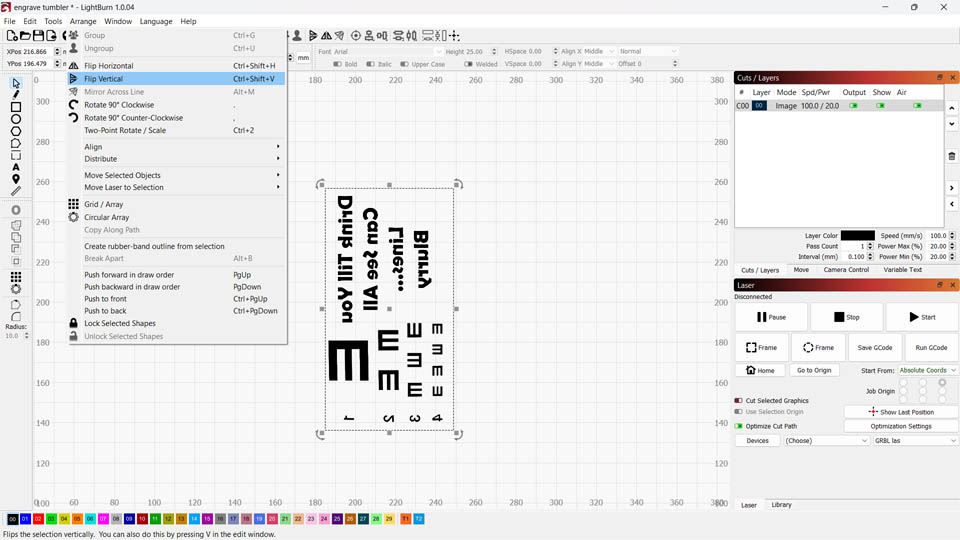
Now, it’s time to apply the mirroring results to the design. To flip the design, with the design selected, click Arrange> Flip Vertical or the keys Ctrl+Shift+V. The image below shows you where to click and how the design looks after I flipped it.
Similarly, if you need to flip the design horizontally click Arrange> Flip Vertical or the keys Ctrl+Shift+V.
Congratulations. You’re ready to engrave. Position the tumbler and laser head correctly and engrave!
For more information, we also have an article on which types of lasers are best for tumblers, which contains a guide with other information and tips and tricks for getting the best engraving results.