
Key Takeaways
- Feed rate and RPM: The main variables to determine for CNC operations. Affect tool life, surface finish, and machining time.
- Cutting speed and chip load: The reference values to calculate feed rate and RPM. Depend on material and tool diameter.
- Formula and modification: The method to get a starting estimate of feed rate and RPM. Need to adjust based on specific operation and machine limitations.
- Trial and error: The technique to find a better set of feed rate and RPM. Experiment with different values until optimal results are achieved.
If you are about to cut or mill anything with your CNC machine, understanding feed rates and RPM speeds is vital.
They will significantly affect your tool life, surface finish, and machining time – so this is a crucial calculation to get under your belt.
In this guide, I’ll provide a strategy for calculating your feeds and speeds that uses the formulas for a starting guess and then modifies the numbers based on your specific operation and machine.
It’s distressing that so much incorrect information exists online on the topic, from articles confusing cutting feed with feed rate to generic formulas that won’t work in practice for your machine.
However, I’ve built this guide based on my experience. If you follow my steps, there should be no reason why you can’t produce accurate feed rate and speed figures easily and consistently.
First, let’s get clear on the real meaning of feed rate, RPM, cutting speed, and chip load, and clarify the differences between these often confused terms.
Feed Rate, Spindle Speed (RPM), Cutting Speed (Surface Speed), and Chip Load
The variables that you need to determine for your operations are your spindle speed (RPM) and feed rate (IPM).
In doing this, we look up two other variables in available tables: cutting speed and chip load.
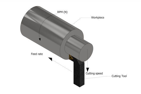
Spindle Speed (RPM)
Spindle speed shows how fast your spindle turns. We define it as the number of revolutions (turns) your spindle makes in one minute (RPM).
Feed Rate
Feed rate shows how fast (the center of ) your bit is moving through your workpiece. Think of when you run a pair of scissors through paper or fabric. How fast you move your scissors is the feed rate.
We define it as the translational speed between your tool and your surface. We express it in inches per minute (IPM) or millimeters per minute (mm/min).
Feed Rate vs Cutting Feed (IPM vs IPR)
There is another variable that is very similar to feed rate.
It is the distance the tool is advanced in one revolution – the cutting feed. So, the unit of cutting feed is inches per revolution (IPR) or mm/rev.
Firstly, when you cut by a spinning machine (as opposed to a knife), these variables carry the same information. Because you can calculate one from the other via this equation:
Feed Rate = Cutting Feed x RPM
However, many confuse cutting feed with feed rate.
One reason for this misunderstanding is that some machinists prefer to work with cutting feed (IPR), and they call it feed rate since it functions the same.
This is okay as long as you are using the correct formula. (We’ll show you the formulas later.)
There are a lot of articles online that use the definition of IPR for feed rate. That has confused a lot of readers regarding the units and the formula.
A huge problem arises when some of these articles give the definition of cutting feed but then use the formula for feed rate. That is when the concepts, the units, and the formulas all fall apart.
Even the Wikipedia page has made this mistake. At the time of this writing, it gives both definitions as feed rate. It even emphasizes the definition we call “cutting feed” as the main definition.
Then, in the formula section, it gives the formula for feed rate even though it had emphasized the definition of cutting feed earlier.
In my opinion, we should stop calling these two variables the same thing to avoid such mistakes. We may choose to work with a different variable, not a different definition.
Still, it is okay to use IPR instead of IPM and call it feed rate since these two variables carry the same information in different units. But thinking they are different definitions of the same formula results in disastrous blunders.
All in all, be prepared to see the definition of similar variables pass as feed rate but mind the formula.
Chip Load (Feed per Tooth)
We have already discussed that you need tables for chip load and cutting speed to decide on your feed rate and RPM.
Chip load per tooth – or simply chip load, or feed per tooth – is the distance that each edge of your cutter moves in one revolution. Its correct unit is inches per tooth per revolution (or mm/rev*tooth).
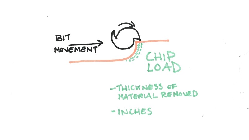
Again, I put the last part in boldface since forgetting that part in the unit is a common mistake I see made in other articles online.
Chip load is how much material each of your cutter teeth can potentially remove every time they turn.
So, when your machine is cutting big healthy chips from your material, you have a big chip load – and when it is giving out dust, you have a small chip load.
We will see later that bigger chip loads keep your tool cooler and increase your tool life, but too big of a chip load can break your tool.
Cutting Speed or Surface Speed
Nearly all the online pages I have checked define cutting speed as the (linear) speed difference between the cutter and the workpiece.
Well, isn’t that awfully similar to feed rate then?
It is no wonder that many people are searching online for the difference between cutting speed and feed rate. And sadly, some of them land on an article that tells them more incorrect information.
Even their units have the same dimension since the unit of cutting speed is feet per minute (FPM) or meters per minute m/min.
Correct Definition of Cutting Speed (Surface Speed) and Differences with Feed Rate
A better definition of cutting speed is the linear speed of the edge of your bit in its rotary motion (for lathes we can use the surface of the turning material).
Or, to adjust the common online definition, it is the linear speed of the cutter relative to the workpiece due to the spindle’s rotation.
If this definition has reminded you of the tangential speed in a circular motion, then you are right. That is the true meaning and definition of cutting speed.
While feed rate measures the speed of your tool in translational motion, cutting speed indicates its speed in rotary motion.
Feed rate shows how fast your servo motors (or stepper motors) move while cutting speed shows how fast your spindle turns the points on the periphery of your tool.
Imagine having your spindle turn your bit in the same position (in your material), then your feed rate is zero, but your cutting speed is not zero. This is because you have pure rotational motion of the tool but no translational motion.
When you are cutting butter with a knife, your feed rate is not zero; yet your cutting speed is zero. This is because you have (almost a) pure translational motion but no rotation.
Difference Between Cutting Speed (Surface Speed) and RPM
You may be wondering about the difference between cutting speed and RPM since they are both measures of your spindle’s rotation speed.
Think of a merry-go-round. All the points on a merry-go-round have the same angular velocity. So, they have the same RPM.
But the further you go from the center on a merry-go-round, the faster the points are moving. So, further away points have a higher linear speed, although they have the same angular velocity.
RPM indicates the angular velocity of your spindle and is the same for all the points of the tool turning with your spindle.
Cutting speed shows the linear speed of the furthest points of the flutes of your tool. Those are the fastest moving points on your cutting edges.
In other words, RPM depends only on your spindle speed while cutting speed depends on your spindle speed and tool diameter.
Effects of Feed Rate and Speed
Feeds and speeds play an essential role in your operation’s results. We will explain these effects here.
As an interesting note, in an acceptable range of feeds and speeds, increasing feed rate has the same effects as decreasing speed. So, when we say you have too high of a feed rate, you can also take it to mean that you have too slow of a speed.
- Too slow of a feed rate reduces your tool life.
You will get larger chip loads with faster feed rates and slower speeds. Bigger chip loads keep your tool cooler.
This is because smaller chip loads mean that you are spending more energy on grinding the material to little particles of dust. This added energy will make your tool hotter. So, bigger chip loads will increase your tool life
- Too fast a feed rate can cause your tool to break.
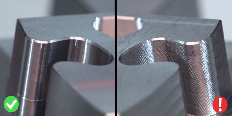
- Too fast a feed rate can cause chatter. Chatter is the unsmooth surface that you get with periodical unevenness. It reflects a vibration between your tool and workpiece.
- Too fast a feed rate results in a poor surface finish.
How to Calculate Feed Rate and RPM
Now, you know the players and you know from the above paragraphs the importance of correct feeds and speeds. It’s time to calculate feed rate and RPM.
The formulas can’t give you perfect results every time. But we will use them to get a starting estimate.
So, we will discuss the reasons for the inadequacy of formulas and investigate how to improve their results.
How to Calculate Feed Rates and Speeds that Beat Formula Results
The good news is that there is a range of correct feeds and speeds. So, our goal is to be in this appropriate range. Then, we can move in this sweet interval to a more optimal feed rate and speed.
Here, I propose how you can find the correct feed rate and speed taking into account your machine’s limitations.
So, I will explain all the problems that could arise and will tell you the remedy for each of them.
Firstly, we need a starting estimate for feeds and speeds. We use the formulas for this estimate. Then we modify the results based on our specific operations.
We can also add trial and error to find a better set of feeds and speeds.
Finally, some CAM software can recommend feeds and speeds based on your material, tool shape, and operation. But you may want to ignore their suggestions based on your machine’s limitations.
So, we consider the limitations of our CNC machine in the four areas that I will explain. Then, we may have to modify the numbers according to our machine’s capabilities.
How to Use the Formulas for Feed Rate and RPM
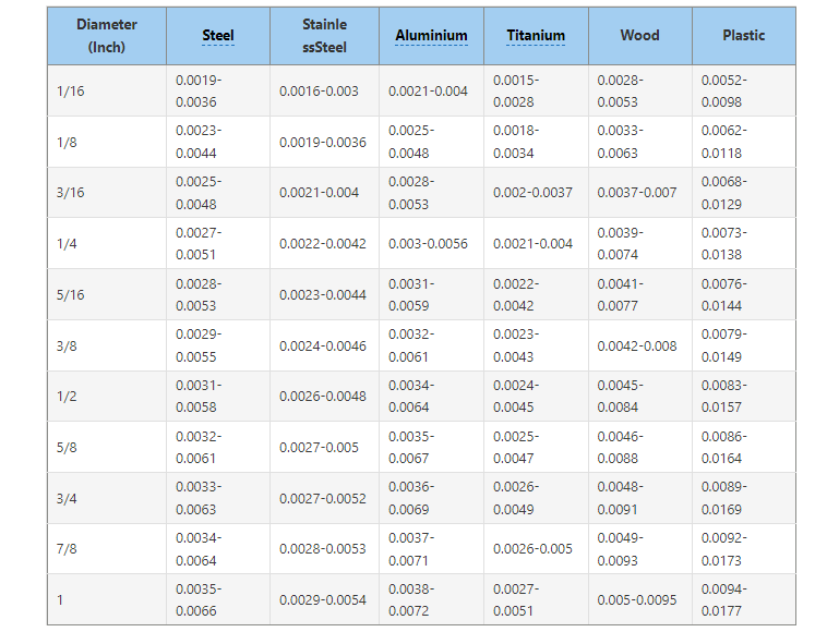
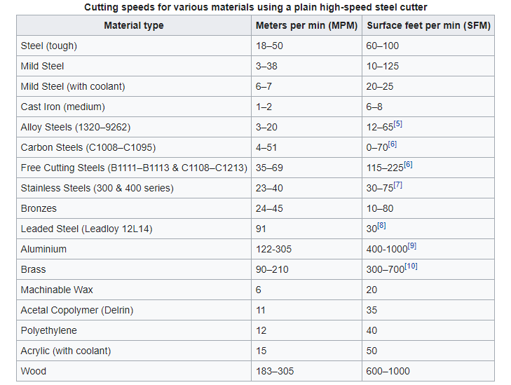
First, we find the appropriate surface speed and chip load in the tables based on our material and tool’s diameter.
Chip Load in Inches per Tooth per Revolution
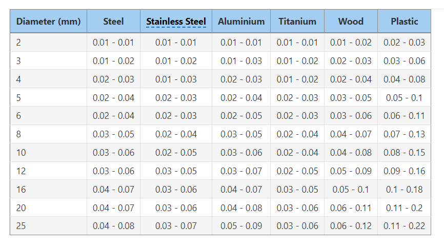
Chip Load in mm per Tooth per Revolution
Surface Speed (Cutting Speed)
Cutting speed depends on the material of your tool. Here is the table for HSS.
Then we use the cutting speed from the table to calculate RPM with one of the following formulas:
Metric: RPM =1000 x cutting speed / pi x D (mm)

where D is your tool’s diameter in mm.
Imperial: RPM =12 x cutting speed (feet per minute) / pi x D (inches)
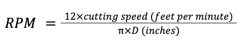
D is your tool’s diameter in inches.
In the next step, we calculate the feed rate.
Feed rate = RPM x chip load x number of teeth
This formula gives you feed rate in IPM or mm/min based on whether you used the metric or imperial table.
If you prefer to use cutting feed (IPR) instead of feed rate, you should remember not to multiply by RPM. So, cutting feed = chip load x number of teeth.
This is why we had insisted earlier to be careful about the definition of feed rate and why a lot of articles are confusing or incorrect, like Wikipedia.
Unfortunately, the numbers you get from these calculations are generally not good enough.
That is because the chip load you obtained from the table is only theoretical. The theoretical chip load tables are based on a scenario of pocketing operation with a flat endmill at a depth equal to your tool diameter with no stepover.
So, your actual chip load may be different in reality. As a result, based on your specific operation, you have to modify the numbers.
Our goal is to keep our actual chip load as close to the theoretical chip load as possible. But we don’t want to step too far from the recommended cutting speeds either.
So, in the following scenarios, you need to adjust your formula results.
- If your tool is plunging deeper than your tool diameter, then you need to use a smaller feed rate. For a depth of twice your tool diameter, you can decrease your proposed feed rate by about 20%.
- Using stepover decreases your actual chip load. So you need to increase your feed rate to bring your actual chip load closer to the theoretical chip load.
By the way, if you are wondering how much stepover reduces your chip load, it depends on the shape of your tool and the amount of stepover. You can read this article to learn more about stepover.
- Finishing has a much smaller actual chip load than roughing. So, increase your feed rate for finishing by about 20% to 30%.
- If you are not cutting with your tool’s entire diameter, such as when you are rimming, you are getting a smaller actual chip load. Once again, you can increase your feed rate to make your actual chip load closer to the theoretical number.
Using CAM for Feeds and Speeds
These days, many CAM programs use formulas that take into account your tool shape, stepover, and step down. So, their recommendations are generally accurate.
Still, you may want to override their feed rate suggestions based on your machine’s limitations – as we will explain.
Trial and Error for Determining Feed Rate and Speed
For the reasons we just explained, you need to modify the numbers you get from the formulas above.
Professional machinists can adjust their feed rate from the sound of the cut. Also, the cut material should be in healthy size chips, not dust.
Besides watching out for the sound and sight of the cut, you can also experiment with feed rates. For this, you can decide on a good RPM with the formula or your machine’s limitations. Also, find an estimate of a good feed rate.
Then, you can increase your feed rate until you see a poor surface finish or chatter. Be careful not to put too much pressure on your tool or it bends and breaks.
When you see that poor surface finish (or hear a bad sound) you can decrease your feed rate a little.
After this, you can do the same experiment with RPM. Only we are decreasing the RPM instead until again, we see that poor surface finish. From there, we can increase our RPM a little.
This way, we are getting as big a chip load as possible to increase tool life.
Feed Rate and Speed When There Are CNC Limitations
RPM Limits
Some spindles or routers present a narrow range of RPMs. For example, your estimate may tell you to work at 10000 rpm but your spindle has a minimum of 12000 rpm.
If you don’t have any of the other problems on this list, you can just move to another point of the acceptable range.
So in this case, you can increase your feed rate as well to keep your actual chip load close to theory.
Remember that to maintain your chip load value, you can increase both the RPM and the feed rate or decrease both of them (proportionately).
But mind that increasing your feed rate is not limited by other issues on this list.
Spindle Power
Your spindle will have to deliver more power when you have deeper cuts, wider cuts (bigger tool diameters), tougher materials, and higher feed rates (or bigger chip loads).
As a result, if you have a strong CNC machine, you can use higher feed rates in the appropriate range. Otherwise, you forget the estimate and start with a lower feed rate that your machine can handle.
For example, if you have a DIY CNC machine with a router that has a DC motor, you may have to choose your feed rate based on your router’s limited power.
CNC Machine Rigidity
Higher feed rates with lower speeds (which yield bigger chip loads) put more pressure on the structure of your CNC machine. So, if your machine is not rigid enough to stand these forces, you may have to lower your feed rate and increase your RPM.
Stepper Motor Limits
Note that stepper motors get weak at high speeds and may begin to miss steps. So, they may pose a limit to how high of a feed rate you can use.
Once again, you may want to determine your maximum feed rate with regard to your motor abilities.
In conclusion, feed rate measures the fastness of translational motion between the cutter and the surface, while cutting speed measures the fastness of the rotary motion between the surface and the edge of your tool.
For any operation, you need to decide on values of feed rate and spindle speed (RPM). To do this, you consult the books on proper values of cutting speed (surface speed) and chip load.
Then you can tap the formulas to get a starting estimate of feed rate and RPM. Next, you modify the numbers based on your specific operation and machine limitations.
Some more articles you may be interested in:
- DXF Files: best sites to download CNC files
- CNC guitar files: best sites
- Profitable CNC projects that make money
- The best wood CNC routers
- The best CNC spindles
- CNC controllers
- How to CNC engrave on granite
- Demystifying how deep can a CNC router cut