
Key Takeaways
- Axis bending: Your axes should not deform under any force, otherwise you will lose some linear motion to heat or rotation. Check your axes by measuring the engraved depth at different points.
- Shear forces: Your axes should resist shear forces that tend to twist them in opposite directions. Check your axes by pushing and pulling them at the ends and see if there is any rotational movement.
- Backlash or belt slack: Your screws and pulleys should engage the nuts and belts without any gap, otherwise you will waste some steps when changing direction. Use anti-backlash nuts and tighten your belts to fix this problem.
- Slant angles: Your axes should be exactly perpendicular to each other, otherwise you will get warped shapes and uneven depths. Check your angles by cutting a square and measuring the diagonals, or drilling holes and measuring the depths.
So, you have built your machine; but you are not satisfied with your CNC machine accuracy. Or, maybe you are in the process of building a CNC machine or 3D printer and are worried that you will only find out your mistakes when it is too late to fix them.
Then you are in the right place.
Here, we will discuss 5 of the most important faults that will jeopardize your CNC machine accuracy. We will also disclose how to check and improve them to get better precision from your CNC or 3D printer.
CNC Accuracy Requires Rigidity Against Bending Forces
This and the next item on the list are due to the most fundamental aspect of a CNC machine: it should be a perfectly rigid body.
Basically, your axes should never deform under any sort of force.
Otherwise, a portion of the power from your motors will store in your axis bend instead of resulting in linear movement.
This causes your machine to cut shorter than it is commanded. Or worse, your axes may bend under your machine’s weight. This way, your machine engraves deeper in the middle of the table and shallower on the sides.
How to Test It
Check your axes: no matter how much perpendicular force you exert on any one of your axes, you shouldn’t be able to bend it in the slightest.
You can run these tests with your machine turned on with your bit on the stock.
This way, if you are able to bend the axis, the bit will bite more into the stock in the direction of your force. So, you will be able to measure the engraved depth and catch your axis bending in the act.
How to Fix It
- Use tough materials like steel.
- Long bars may need reinforcement.
- If in doubt, use hollow square bars. The square cross-section provides the highest rigidity per weight.
CNC Accuracy Requires Rigidity Against Shear Forces
This one is also another feature of a rigid body, but the type of deformation is different here.
Let’s say, you already have linear mechanisms that allow movement in one direction only. But, is the axis you have built with them rigid enough to stand shear forces?
Shear forces tend to move one part of a body in one direction while moving some other parts in the opposite direction. Like when you tear a piece of paper; or when you squeeze a piece of cloth by turning your hands in opposite directions.
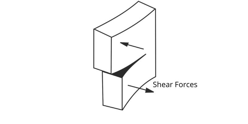
If your axis yields to shear forces, some of the linear motion will instead be lost to rotation. Shear forces are stronger away from the center of mass of your machine.
So for example, you will get a bigger error on the sides of the table.
How to Test It
To test this, pick any axis you want to test; say, Y-axis; and examine it with the shear forces in a plane containing your axis, let’s say, the XY plane.
Here’s how you do it.
At the side of the gantry (the ends of the X-axis), if you push in the direction of +y in one end, while pulling in the direction of -y in the other end, there should be absolutely no rotational movement.
In other words, your gantry should not move forward at one end, while moving backward at the other end.
If you have this problem, there is deformation in your gantry due to shear forces. You can test other axes similarly in their respective perpendicular planes.
How to Fix It
- Use tough materials like steel.
- Build resistive arms for shear forces. To do this, rigidly connect two linear bearings on each side of your axis. Their distance is your resistive arm; and the longer it is, the more resistance it creates against shear forces.
Reduce Backlash or Pulley/Belt Slack
If you have successfully created a rigid body, one main meaningful position error you can get in your CNC machine, 3D printer, or laser cutter could be due to backlash or belt slack.
How to Test It
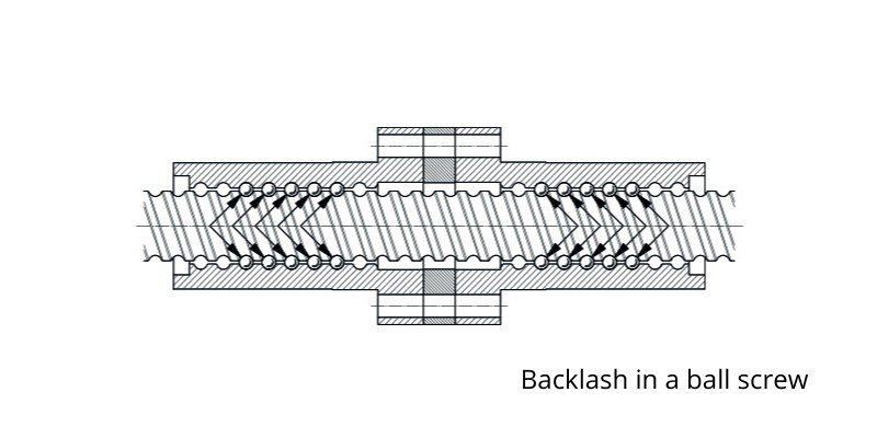
Backlash is a short distance the screw has to travel before it can engage the nut. On bigger screws and nuts, you can feel it by linearly moving the nut back and forth without turning it.
This distance will create an error in linear travel.
Because every time your motor changes direction, its first few steps are wasted while your machine stands still instead of moving. Similarly, a pulley may turn a short distance before it can engage the belt.
How to Fix It
- For screw-nut assembly, the remedy is to use a tighter lead-screw or ball-screw in the form of anti-backlash nuts.
- For pulleys, you may tighten your pulley-belt sets to specified standards.
Accurate Calibration for CNC Precision
This one is the easiest to fix. All you need to do is have your stepper motors move a certain number of steps.
For good measure, you can even push the machine parallel to the direction of motion before the movement starts and at the end; so as to cancel any significant backlash effects.
Next, measure the distance covered and determine the distance per step. Then, calibrate your controller accordingly.
Fixing Slanting Axes for CNC Accuracy
Your three linear axes should be exactly perpendicular, especially your X and Y axes; otherwise, the X-Y error reflects in almost anything you do with the machine.
If your X and Y axes are not exactly square, when you cut a circle you get an ellipse instead. Or when you cut a rectangle you get a parallelogram. Basically, all the shapes you cut or engrave will be warped.
Additionally, if your Z-axis is not at a right angle with your XY plane, you will engrave deeper on one side of the table and shallower on the other side.
Plus, your router bit must also be perpendicular to the XY plane; but we consider that as a special case of your Z-axis perpendicularity.
How to Test It
You should check for your machine slant in the following order.
Firstly, to check for the perpendicularity of your Z-axis to the XY plane, you need to have your machine drill a certain depth at these three points: (0,0), (xf,0), (0,yf).
Here, xf and yf can be any values near the end of your axes.
If the drilled depths of these points are not exactly equal, you have a slant problem. You can divide the depth difference by the covered distance to calculate the XZ and YZ slant.
Secondly, you should test for the perpendicularity of your X and Y axes; for which, a lot of methods come to mind. The one I thought of while trying to correct this problem in my machine is this:
Cut a square from your stock.
Then, measure the two diagonals; they should be exactly equal.
In case they are unequal, you have a rhombus in your hand, instead of a square. Let’s say that the diagonals of your piece are a and b. Then, the actual angle between your axes is 2arctan(a/b), as illustrated in the exaggerated image below.
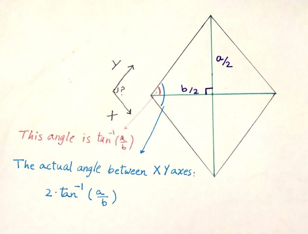
So, the difference between this angle and a right angle is your slant error.
How to Fix It
- Measure your slant angles with the methods described above.
- Hardware Solution: Design your machine with the ability to calibrate slant angles later. Implementing mechanisms for calibration will allow you to calibrate your machine using the formulas given above.
- Software Solution: In theory, by knowing the slant angles, it is easy to use linear algebra to create a transformation matrix to map cartesian coordinates to a slanted coordinate system. But I have no information on whether some of the CAD software out there include this capability. If you guys have that knowledge, don’t hesitate to share it with us. But bear in mind, no software will be able to help you if your router bit is not perpendicular to your XY Plane.
At long last, achieving precision is the holy grail of DIY CNCs, 3D printers, and laser cutters. Here, we mentioned 5 of the most important sources of inaccuracy.
Hopefully, you can improve your CNC machine accuracy (or your 3D printer) by eyeing the items mentioned here.
Other articles you may be interested in:
- Stepover in CNC CAM
- The best CNC software (including CNC control software)
- The best CNC routers
- The best metal CNC machines for aluminum
- The best sites for DXF CNC files
- Best CAD-CAM software
- How to CNC engrave on granite