The controller is the brain of any CNC, 3D printer, or laser. The CNC controller interacts with the control software to receive the G code and then plans the motion of your stepper motors. Then it controls the motors and reports back to the control software.
In our previous article, we showed you how to move your stepper motors with an Arduino board and provided code to test your setup. It is time to turn your Arduino board into a CNC, 3D printer, or laser controller.
We will show you how to make two different CNC controllers: GRBL, and G2Core. They are both open source and free firmware. We will compare them thoroughly so you can decide which one is better for you.
You need to make a CNC controller if:
- You are building a DIY CNC machine (or laser, or 3D printer), so one of the most important parts is to build its controller.
- You already have a 3D printer, laser, or a CNC like ShapeOko, X-Carve, or PROVer and have deleted the firmware on your GRBL or damaged the board.
- You are upgrading to a newer version of GRBL.
- You are using your computer as a CNC controller with Mach or LinuxCNC, but you are wondering whether you can build a real dedicated DIY CNC controller.
- You want to change your controller to a GRBL or a G2core.
What’s more, if you want to upgrade your stepper motors, but your current CNC shield cannot provide enough power for them, you should read our previous article and learn DIY wiring a CNC controller.
Arduino Controller vs Parallel Port
There are two main methods of building a DIY CNC controller: turning your computer into a CNC controller or building a dedicated controller on your CNC with an Arduino board.
Short of buying an industrial controller, turning a computer into a CNC controller with Mach or Linux CNC was the only way for DIYers.
Then the easily programmable Arduino boards and open-source control firmware such as GRBL and TinyG2 surfaced. GRBL and G2Core (TinyG2) run on Arduino boards and act as dedicated CNC controllers. We will compare these two methods in another article.
GRBL vs G2Core
We will show you how to make both of these controllers. But we clarify their pros and cons so that you can carefully decide which one better suits your purposes.
Basically, if both controllers can do your job, choose GRBL. It’s much more convenient than G2Core. While G2Core has some annoying issues, GRBL is bug-free, functional, and enjoys great support.
On the other hand, G2Core is more powerful than GRBL, capable of doing much more, and able to grow gigantically in the future. Since about 90% of its memory and fast CPU is unused, it can accommodate tremendous development in the future. But it has several issues that should be fixed.
Meanwhile, development has been slow, and some simple issues have been left unfixed for years.
So, if you have a 3-axis CNC, 3D printer, or laser, GRBL is the better choice for you.
But if you need a controller for a CNC machine with more than 3-axes or several dual-axes, go for G2Core because GRBL can’t do the job.
Read more: GRBL vs Mach3 for CNC
Advantages of GRBL over G2Core
- Control Software. GRBL enjoys a plethora of control software. OpenBuilds control, CNCjs, UGS (Universal G Code Sender), ChiliPeppr, Easel, and some more software can work with GRBL free of bugs. But your GUI option for G2Core is pretty much only ChiliPeppr. Collterm version 1.4.3 works with it too but it is primitive and text-based.
- Persistent Machine Settings. When you tell GRBL your machine settings, it remembers it forever. But you have to copy and paste your machine settings every time you connect to G2Core, which is annoying. The developers have not fixed this issue for years.
- Easy to Flash. Flashing GRBL is so easy that you can do it in minutes with Arduino IDE. But Arduino IDE cannot flash G2Core. Not only is it more complicated, but also Synthetos’s pages do not explain things straightforwardly. However, this article tells you how to do it simply.
- Ready Settings. If you have a CNC or laser that comes with GRBL (such as an X-carve), you can download GRBL from their website with the machine settings already defined.
- Plenty of Support. Obviously, if you were a manufacturer like ShapeOko, you would never use a controller like G2Core that demands its user to define machine settings every time. So, they use GRBL and as a result, there is plenty of support for GRBL out there.
- Price. Both GRBL and G2Core are free firmware. But the hardware for G2Core is Arduino Due which is more expensive than Arduino Uno for GRBL.
Advantages of G2Core over GRBL
- GRBL can only control a 3-axis CNC (XYZ) while G2Core can control even a 6-axis CNC (XYZABC).
- The latest version of GRBL (v1.1) can control up to 4 stepper motors whereas G2Core can control 6 stepper motors. So, G2Core supports dual-axis control.
- G2Core allows buffer wipe. Both GRBL and G2Core have feed hold commands to stop your machine’s movement. But you can also send “%” to G2Core to wipe its buffer and break its cycle. This is also handy in jogging your machine.
- G2Core generates a much smoother stepper motor motion. (GRBL uses AMASS algorithm but G2Core generates jerk-controlled motion with 5th order DE).
- GRBL is pretty much all it can be but G2core has a lot of room to grow. It has voluminous free memory and pins for further development.
- GRBL uses the same enable pin for all stepper motors but G2Core controls motor powers separately.
- There is only one limit switch pin in GRBL for each axis, but G2Core has two. (So, with GRBL you have to put your limit switches in series.)
- Hardware. GRBL runs on Arduino Uno while G2Core runs on Arduino Due. Arduino Due (that can host G2Core) has a much faster CPU with a much larger memory than GRBL’s Arduino Uno. (Due has a 32-bit ARM CPU at 84 Mhz while Uno has an 8-bit AVR that works at 16 MHz).
Now that you have chosen your controller with the help of this comparison we tell you how to make these controllers.
How to Flash GRBL to Arduino Uno
Step 0. Buy an Arduino Uno
The Arduino Uno is a cheap electronic board with a microcontroller that will become your CNC controller.
![Arduino UNO REV3 [A000066]](https://m.media-amazon.com/images/I/51txW1iicVL._SL500_.jpg)
It should come with a USB-A to USB-B cable.
Step1. Download Arduino IDE
You need to install Arduino IDE for free from here. It’s best to get the most recent version.
Step 2. Download GRBL
You can download the GRBL firmware from Github. You can also download the newer version GRBL 1.1 from here.
To download from Github, click on the green button that says code, then download the zip file. Then extract the zip file somewhere on your computer. It creates a grbl-master file.
Now, open the Arduino IDE. Click on the sketch tab >> include library >> Add .Zip Library…

Browse to the location on your computer where you extracted GRBL and open the grbl-master folder.
Then, click on the folder “grbl.” Then click Open. Arduino IDE will show you a message that it added the library.
Step 3. Connect to Your Arduino Uno Board
Now, plug your Arduino Uno board into your computer’s USB. After the computer recognizes the board, go to Arduino IDE again.
Now choose the Arduino Uno board: click Tools. You will see a line in the drop-down menu that says Port: COM(some number, mine was on COM3) (Arduino/Genuino Uno) >> COM(some number) (Arduino Uno/Genuino)
Step 4. Flash GRBL to the Arduino Uno Board
Now, in the Arduino Uno IDE, go to the “File” tab and click File >> Examples >> grbl >> grbl Upload.
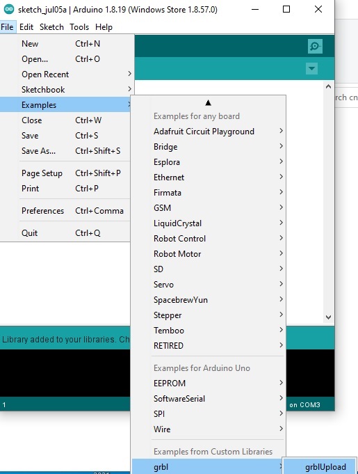
A new window will pop up. Click on the green arrow that says upload. Wait a few seconds to get the “Done uploading” message.
Congratulations, your raw Arduino Uno microcontroller has turned into a CNC controller (GRBL).
Step 5. Connect Your Hardware (CNC, 3D Printer, or Laser)
We have explained in our previous article how to connect your Arduino to stepper motors. We have also provided the GRBL pinout in that article.
Step 6. Define the Machine Settings
You can connect to GRBL with control software such as UGS and put your machine settings into GRBL. You can also do it with Arduino IDE.
In Arduino IDE click Tools >> Serial Monitor. A window pops up. At the bottom of this window set the baud rate to 115200. You will see a message that says Grbl. ‘$’ for help.
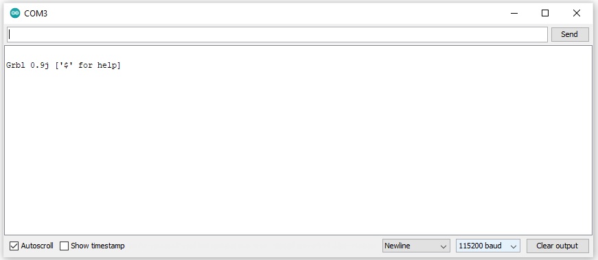
If you type $ now, it will show you the appropriate command for each GRBL setting.
Perhaps, the most important setting you have to tell GRBL is your machine’s steps per mm. If you need help calculating steps per mm, I will tell you how to do it at the end of the article.
How to Make a G2Core Controller
You need an Arduino Due to make a G2Core controller. But Arduino IDE does not support the Due and learning to flash G2Core from Synthetos’s page is a headache. But I’ll show you how to do it simply.
Step 0. Buy an Arduino Due
The Arduino Due is a powerful microcontroller board that uses an ARM processor.
It should come with a USB cable.
Step1. G2Core Bin File
Visit this page. There is a dropdown menu called “compare” on the right. Click that and choose the last stable version of G2Core.
At the time of this article, the last stable version is 100.xx (This page states what the latest version is).
Download the G2Core bin file.
Step 2. Download Bossa
Download Bossa for free from here.
Step 3. Flash G2Core
Your Arduino Due has two USB type B ports. One of them is the “programming port,” and the other is the “native USB” port. See the left side of the image below.
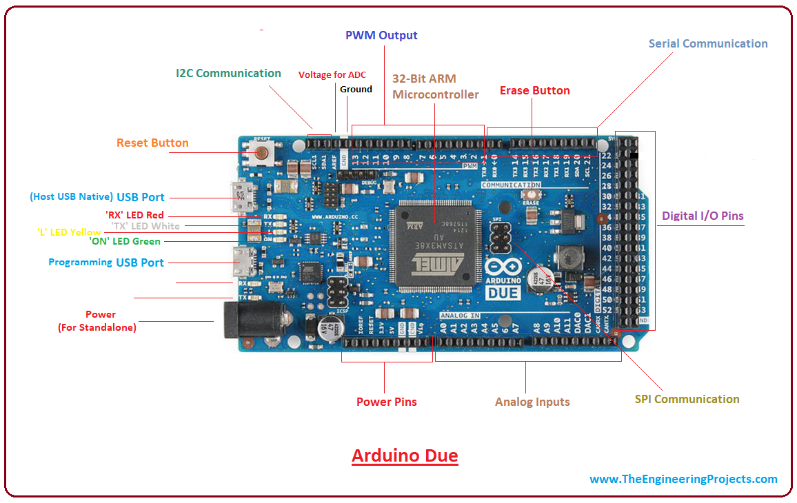
Connect the USB cable to the programming port of your Arduino Due. This port is closer to the reset button. Now connect the other side of the cable to your computer.
See what COM port the Arduino Due comes on. Open Bossa and choose the COM port under “Serial Port.”
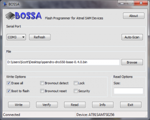
Under “File,” browse to the location of your bin file. Then click on “Write.” When you have finished flashing, unplug the USB cable from the programming port and connect it to the native USB port. This port is closer to the power plug.
Now, press the Arduino’s reset button.
If you are using Windows 10 or OSX, you don’t have to do anything else. But if you are using Windows 7, right-click on this link and click “save as” to download the G2Core driver for windows.
Then open your computer’s device manager >> Ports (COM & LPT)
You will see Arduino Due’s serial ports here. Update them with the driver you just downloaded.
Congratulations. You have a G2Core controller.
Step 4. Connect Your Hardware (CNC, Laser, or 3D Printer)
We have explained how to connect the Arduino board to your stepper motors in our previous article. We have also provided the G2Core pinout in that article.
Step 5. Define Machine Settings for G2Core
There are unsolved issues with G2Core. Every time you connect to it, you have to press Arduino’s reset button.
Plus, you have to define machine settings after each connection because G2Core loses this data every time you disconnect its power.
So, save your machine settings in a text file so that you can copy and paste them every time you connect to G2Core.
This page and the pages it links to explain the different machine settings in G2Core. Once again, these pages do not explain things in simple terms.
So I have gathered the most important machine settings for you so that you can save your text file. These are example numbers. They depend on your particular machine. But I explain what they mean.
Copy the commands on the left column in a text file (with appropriate numbers).
| Example Text in Your Text File | What It Does |
|---|---|
| {gun:1} | 1 is for units in mm and 0 is for inches. |
| {1:{ma:0}} | The Arduino pins of motor 1 will be the X-axis. (You can choose any other axes: Y=1, Z=2, A=3, B=4, C=5) |
| {2:{ma:1}} | The Arduino pins of motor 2 will be the Y-axis. |
| {3:{ma:2}} | The Arduino pins of motor 3 will be the Z-axis |
| {1:{su:50.43508}} | The steps per mm for motor group 1 is 50.43508. |
| {2:{su:50.43508}} | The steps per mm for motor group 2 is 50.43508. |
| {3:{su:50.43508}} | The steps per mm for motor group 3 is 50.43508. |
| {1:{po:0}} | Motor 1 should turn clockwise to go in the direction of its axis. If you change 0 to 1 the correct motor direction will be counterclockwise. |
| {2:{po:1}} | Motor 1 should turn counterclockwise to go in the direction of its axis. |
| {3:{po:1}} | The same thing for motor 3. |
| {xvm:2000} | The maximum speed on the X-axis is 2000 mm/min. |
| {yvm:2000} | The same thing on the Y-axis. |
| {zvm:2000} | The same thing on the Z-axis. |
| {1:{pm:2}} | Only power motor 1 during a cycle and de-energize it after finishing the job. If you change to pm:1, the motor will always be powered. Also, pm:0 will disable that motor. |
| {2:{pm:2}} | Same only for motor 2. |
| {3:{pm:2}} | Same only for motor 3. |
How to Calculate Steps per mm of Your CNC, Laser, or 3D Printer
There is a formula that yields the steps per mm of your CNC from the hardware (ball screw pitch, gear ratio, stepper motor steps per revolution). But you don’t need to calculate any of these.
Let’s say we want to find steps/mm of the X-axis of a machine whose X-axis length is 40cm.
Start with a guess for the steps per revolution. 40 is a good guess, so set your steps/mm to 40. Now send G code to move your machine a short length: for example, 10cm = G1 X100.
Measure how much your machine has moved, 8.2cm for instance. Now modify your steps/mm:
New steps/mm = (intended length/actual length)* old steps/mm
In our example: steps /mm: (10/8.2)*40 = 48.78049.
This number is very close. Home back your machine to X=0. To fine-tune it, move your machine longer this time (for example 35cm). Allow some room from the other edge:
G1 X 350 (move 35cm)
Now measure how much your machine has moved. Let’s say it has moved 35.1cm. Modify once more:
steps/mm = (35/35.1)*48.78049 = 48.64151.
That’s it. Put the new number in your machine settings and find steps/mm for your other axes.
Summary
In our previous article, we showed how to connect the hardware of a CNC, laser, or 3D printer controller.
Now, if you want to make a dedicated controller for your CNC, laser, or 3D printer, you can turn an Arduino board into a CNC controller.
We have shown you how to turn an Arduino Uno into a GRBL controller, or an Arduino Due into a G2Core controller. Both GRBL and G2Core are free firmware.
GRBL is more convenient, easier to flash, and has plenty of support and control software. On the other hand, G2Core is a 6-axis CNC controller that generates a very smooth stepper motor movement. Also, it supports dual-axis control.
Finally, we have explained how to calculate your machine’s steps/mm. So, these articles provide enough information to make your DIY CNC, laser, or 3D printer controller.
Related posts:
- Stepover in CNC and CAD CAM
- Wiring stepper motors (with 4, 5, 6, 8 wires)
- Best stepper motors for CNCs
- Things that affect CNC accuracy (and how to fix them)
- The truth about CNC feeds and speeds (and how to actually calculate)
- The best GRBL software for CNC and laser controllers